

 English
 中文简体
中文简体

Industry News
Home / News / Industry News / Closed Die Forging: Process, Materials, Tolerance and Supplier Selection
 Home / News / Industry News / Closed Die Forging: Process, Materials, Tolerance and Supplier Selection
Industry News
Closed Die Forging: Process, Materials, Tolerance and Supplier Selection
2026-09-10
Closed die forging creates components with better internal grain flow than machining from bar, and for medium to high volumes the per piece cost usually drops below machined alternatives. In this process, heated metal is pressed into a pair of shaped dies that fully enclose the workpiece, forcing the material to fill the cavity with each stroke. Once you understand how that changes strength, material waste, and production speed, you can make smarter sourcing decisions for gear shafts, flanges, wheel hubs, and other critical parts. This article gives you the practical details, including process steps, material options, tolerance expectations, and supplier criteria.
Content
How Closed Die Forging Works
The principle is simple: a block of metal is heated above its recrystallization temperature, placed in a bottom die, and struck by a top die that drives the material into the cavity shape. In a typical press or hammer operation, the sequence follows these steps:
- Cut the bar or billet to calculated volume and heat it to forging temperature (for steel, usually 1050 to 1250 degrees Celsius; for aluminum, 400 to 500 degrees Celsius).
- Perform a preforming or blocker operation to distribute metal toward high-fill areas.
- Run the finish die to form the final geometry; excess material escapes as flash.
- Trim flash in a trimming press, and sometimes perform coining or sizing for tighter tolerances.
- Heat treat the forging by normalizing, quenching, and tempering to meet required mechanical properties.
The dies are made from low alloy tool steel, typically pre-hardened, and their geometry defines draft angles, radii, and machining allowance. Because the metal flows rather than being cut, grain lines follow the part contour, which improves resistance to bending and impact loading. Manufacturers with multiple hammer sizes, such as ACE's 3 ton, 5 ton, and 15 ton electric hydraulic hammers, can select the right tonnage for each component.
Why Closed Die Forging Beats Machining for Load-Bearing Parts
If your component will carry bending or fatigue loads, choose a closed die forging over machining from bar stock. Cutting a shape from solid bar creates a discontinuity where the grain fibers are severed, while forging bends the fibers around the part shape. The practical result is higher fatigue strength, better impact toughness, and fewer failures in service. That advantage matters most for crankshafts, gear shafts, connecting rods, and similar parts. For simple low-load parts, machining can still be cost-effective.
Material utilization is another clear difference. A typical closed die forging uses 80 to 90 percent of the starting material, whereas machining from bar often leaves 40 to 50 percent as chips, depending on part complexity. The chart below shows typical ranges.
The chart shows that closed die forging and casting retain most of the input material, while machining from bar stock removes a large share as chips. A closed die process often lands in the 80 to 90 percent range because the flash is trimmed and recycled. Open die forging uses a simpler tool set but less material efficiency, since the shape is produced through controlled deformation and often leaves extra stock. Machining from bar is the least efficient when a complex contour is created by subtracting material. For high-cost alloys, the raw material savings from closed die forging can offset the tooling investment within a modest production run. This is why buyers working with stainless steel or nickel alloys often compare forging quotes with machining quotes before finalizing a design.
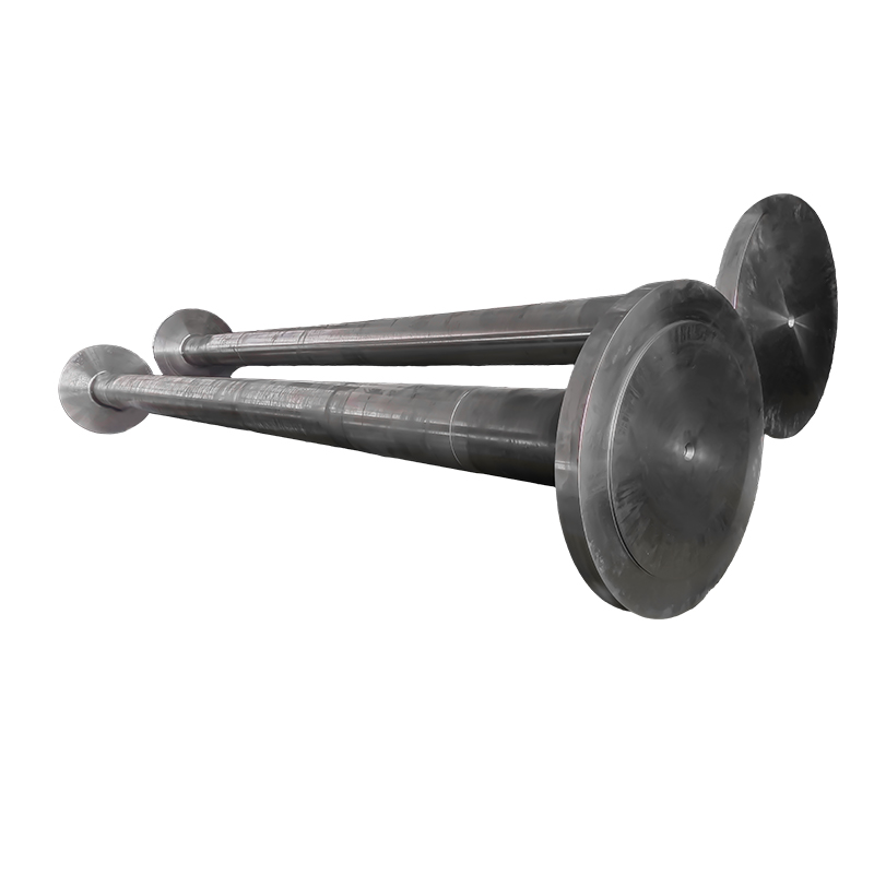
For a gear shaft, the closed die route produces a grain flow that wraps around the tooth roots, giving a measurable advantage in bending fatigue.
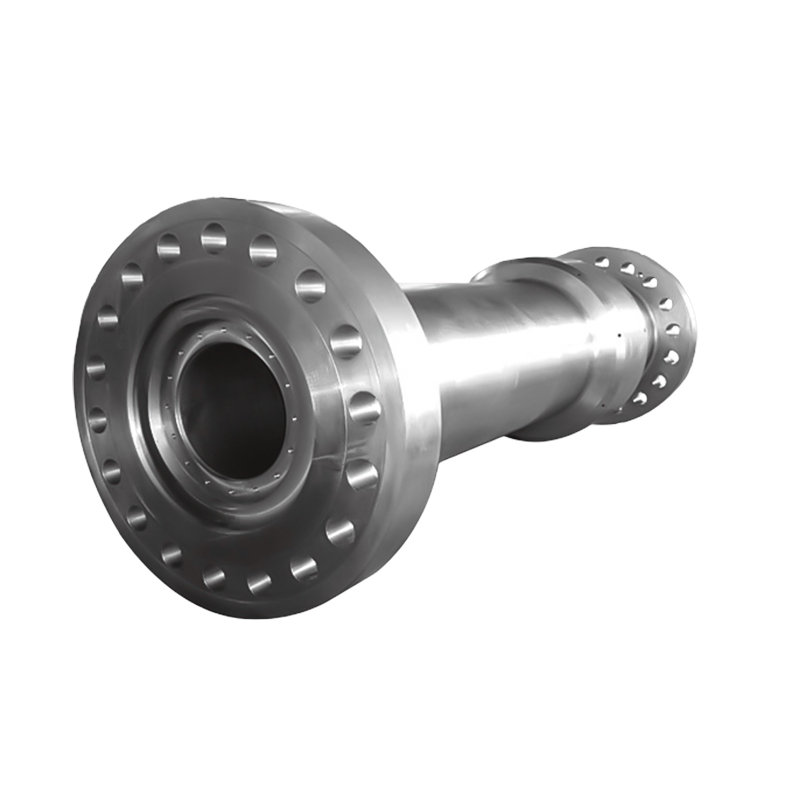 Closed Die Gear Shaft Forgings for Marine and Port EquipmentHigh-strength alloy gear shaft forgings with integrated shaft and gear design, suited for seawater corrosion resistance and heavy loads in port cranes and ship deck machinery.View Product →
Cost behavior at different volumes
Upfront tooling changes the cost picture. A closed die set can cost thousands of dollars, but the per piece forging cost is low and stable once the die is paid for. Machining has a smaller tooling barrier but a higher variable cost per piece. The crossover usually happens between a few hundred and a few thousand parts, depending on geometry and material. The graph below shows the general shape of the two cost curves.
The crossover point marks the volume where a closed die forging becomes cheaper per part than machining. Before that point, the die amortization makes forging look more expensive; after it, the lower material waste and faster cycle time win. For a simple part, the crossover may be around 500 units; for a complex stainless steel component, it can be below 300 units. Buyers should ask for both tooling amortization and piece price instead of comparing quoted unit prices alone. Many forging suppliers quote tooling separately, so the total cost curve is more meaningful than a single number.
Materials Used in Closed Die Forging
Most closed die forgings are made from carbon steel, alloy steel, stainless steel, aluminum, brass, and titanium. Steel remains dominant because it combines strength, cost, and predictable response to heat treatment. The table below summarizes common choices and typical applications.
| Material | Typical grades | Common applications |
|---|---|---|
| Carbon steel | 1020, 1045, 1060 | Shafts, gears, connecting rods |
| Alloy steel | 4140, 4340, 8620 | Heavy-duty gears, axles, crane parts |
| Stainless steel | 304, 316L, 420 | Marine, food, chemical equipment |
| Aluminum | 6061, 7075 | Aerospace fittings, lightweight brackets |
| Titanium | Ti-6Al-4V | Aerospace, medical, high-performance sports parts |
If your design uses stainless steel, forging must be done within a specific temperature window to avoid grain growth and carbide precipitation. Some stainless grades require a post forging anneal to restore corrosion resistance. For the correct process details, see our guide on forging stainless steel. A good example is the SS316L impeller wiper forging used in food and feed machinery, where both corrosion resistance and wear resistance matter and the forging route keeps grain flow aligned with the blade shape.
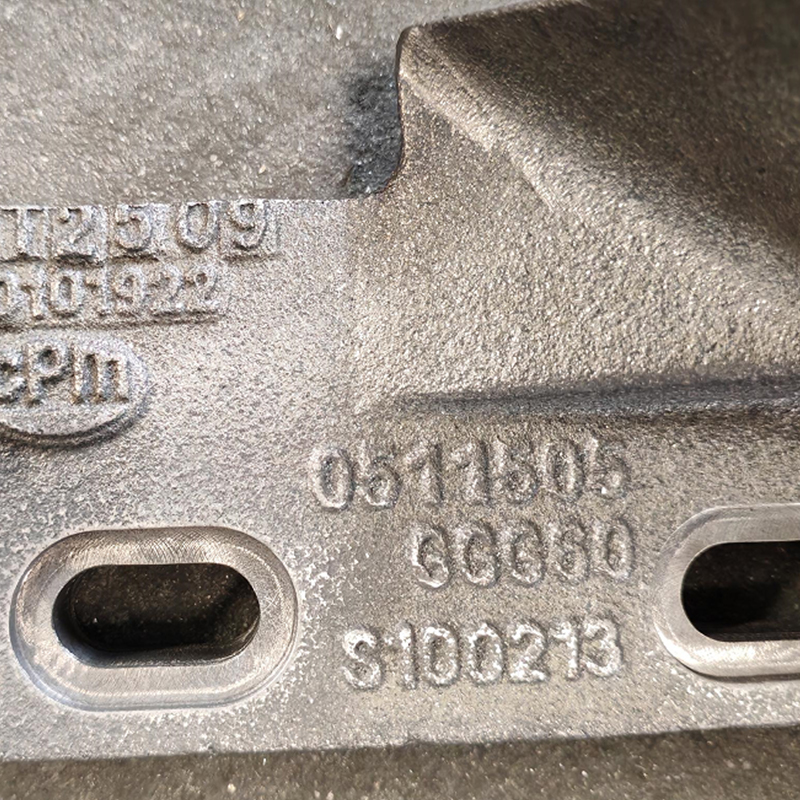 SS316L Impeller Wiper Forgings for Material Flow OptimizationThese stainless steel flow deflectors improve flow path and distribution in feed machinery, offering wear, heat, corrosion, and fatigue resistance for stable operation.View Product →
Where Closed Die Forgings Are Used
Closed die forgings appear wherever reliability matters: wind turbine gearboxes, marine propulsion shafts, crushers, excavators, high pressure valves, and food processing equipment. In wind turbines, planetary gears and sun gears are often forged to support cyclic loads for 20 or more years. In shipbuilding, intermediate shafts and stern shafts are forged because a broken shaft is unacceptable at sea. For mining, crusher spindles and excavator track links must resist impact and fatigue. In petrochemical plants, valve bodies and flanges face high pressure and corrosive media.
This is why ACE offers dedicated product lines for electric power, ship and port machinery, mining, petrochemical, and food industries. You can review the entire forge product range to see standard dimensions and available steel grades.
For wind turbine gearbox applications, the combination of size and fatigue loading makes closed die forging the preferred route for sun gears and planet carriers.
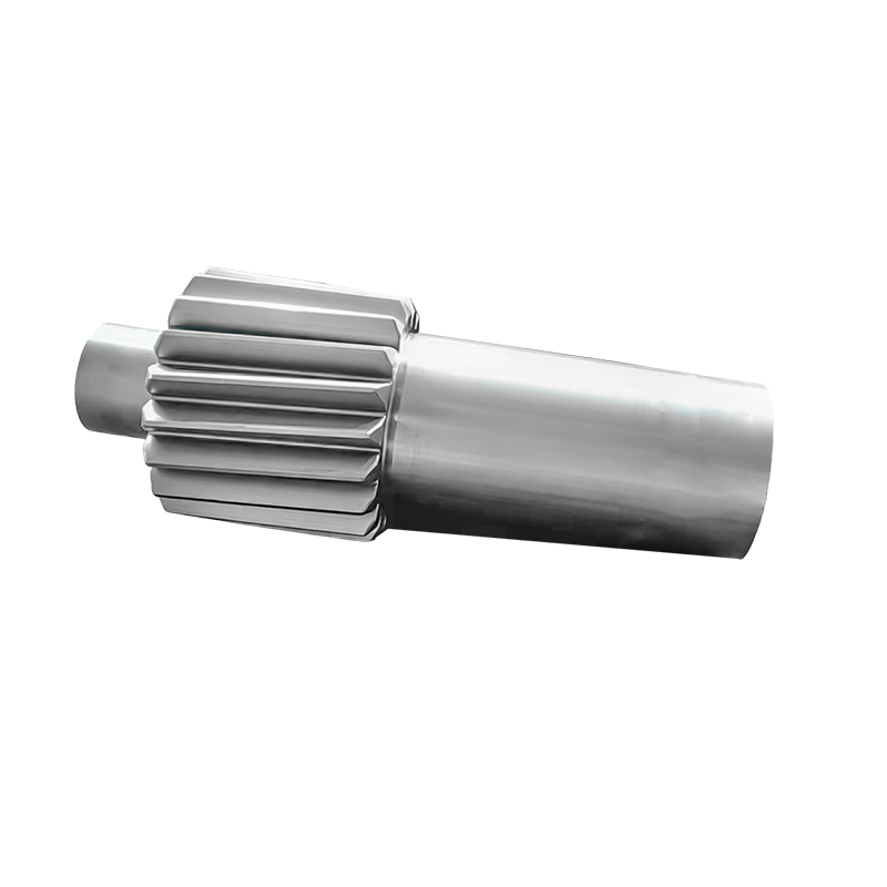 Large Wind Turbine Sun Gear Forgings in Carburized SteelPrecision-forged sun gears made of 18CrNiMo7-6 with high surface hardness and core toughness, designed for multi-megawatt gearboxes to handle cyclic loads and impacts.View Product →
Tolerances, Die Life, and Part Limits
Closed die forging achieves typical tolerances of plus or minus 0.5 to 1.5 mm for small parts, and the tolerance range increases with the overall size. Die life depends on forging temperature, material, die material, and lubrication. Carbon steel parts commonly run 5,000 to 15,000 parts per die set, while nickel alloys may reduce die life to fewer than 2,000 hits. This is why die coatings and proper cooling are critical in a production shop.
The fatigue advantage of forging is visible in relative performance tests. The chart below compares the fatigue strength of a closed die forging, a machined bar component, and a casting.
The comparison is normalized to a closed die forging at 100 relative points. Machining from bar retains about 80 percent that level because machining cuts through the grain fibers that carry bending loads. Casting comes in near 65 percent, depending on porosity and solidification defects. The numbers are not absolute material properties; they represent typical differences in fatigue behavior under the same stress cycle. This is why safety-critical components such as steering knuckles, gears, and crane parts specify a forged blank whenever production volume justifies the tooling.
How to Select a Closed Die Forging Supplier
Look beyond the lowest quote. Evaluate a supplier across material utilization, mechanical strength, surface finish, design flexibility, and cost efficiency at volume. The radar chart below compares closed die forging with machining for a typical load-bearing part; the closed die polygon is much wider on strength and cost, while machining wins on surface finish and design flexibility.
The radar chart condenses a process comparison into five dimensions. Closed die forging shows a strong advantage in material utilization and cost efficiency at volume, which is why it dominates mass produced critical parts. Machining from bar still wins on surface finish and design flexibility, especially for prototypes and low quantities. The narrower machining polygon explains why mechanical strength is lower when grain flow is cut. Use this framework to weight your own requirements: if fatigue is critical, forging should rank higher. If you need one-off prototypes or fast design changes, machining may be the safer route.
- Check equipment tonnage. Hammer sizes determine maximum part weight and die stroke; ACE operates 3 ton, 5 ton, and 15 ton electric hydraulic hammers plus 1 meter and 1.5 meter ring rolling mills.
- Look for in-house heat treatment and finish machining. This reduces lead time and avoids double handling between subcontractors.
- Ask about non-standard custom forging. If your drawing is outside a standard catalog, a supplier with custom die design experience can optimize material placement and reduce machining allowance.
- Review quality documentation. Confirm how the supplier inspects first articles, controls heat treatment, and tracks material traceability.
- Evaluate production capacity. A dedicated forging plant with expanding capacity supports stable delivery for both prototypes and scheduled batches.
Message Us Right Now!
-
Mobile Terminal
-
Quick Links
Products About Us Equipment & Capacity Quality News Contact Us -
Product Category
Power‑Generation Forgings Ship and Port Machinery Forgings Mining and Metallurgy Forgings Food and Feed Machinery Forgings Welding Fabrication Petrochemical Industry Forgings CUSTOMIZED MADE FORGING PARTS -
Contact Us
Mob.: +86-173 7218 0878 Tel.: +86-515-8389 0396 E-mail: ivy.zhai@aceprocess.cn Add.: No.21 Jinfeng Road, Economic Development Park, Dafeng District, Yancheng City, Jiangsu, China
Copyright © 2025 Yancheng ACE Machinery Co., Ltd. All Rights Reserved.
China open die forgings manufacturer
custom precision forgings supplier
