

 English
 中文简体
中文简体

Industry News
Home / News / Industry News / Forged Rotor Shaft Guide: Grain Structure, Process Steps and Selection Tips
 Home / News / Industry News / Forged Rotor Shaft Guide: Grain Structure, Process Steps and Selection Tips
Industry News
Forged Rotor Shaft Guide: Grain Structure, Process Steps and Selection Tips
2026-09-04
A generator rotor shaft almost never fails without warning, yet when a teardown report arrives, the root cause usually traces back to decisions made at the forging stage: internal porosity that was never closed, grain flow sliced away at a stepped shoulder, or a heat treatment cycle that hardened the surface while leaving the core weak. Those are precisely the failures a properly forged rotor shaft is designed to prevent.
This guide explains what a forged rotor shaft is, why forging outperforms casting and bar stock for rotating parts, how the sequence runs from heated billet to balanced assembly, and which specifications a buyer should lock down before signing an order.
Content
What a Forged Rotor Shaft Is and Where It Works
A rotor shaft is the rotating backbone of an electric machine. It carries the laminated core or field winding of a motor or generator, spins in its journal bearings, and transmits full torque while resisting bending loads, axial thrust, and repeated thermal cycles. Because those stresses reverse millions of times over a service life, the internal quality of the material matters as much as the surface finish.
A forged rotor shaft is one shaped from heated steel under heavy pressure, on a hammer or press, so that the metal grains align with the working stresses instead of forming randomly. Typical applications include:
- Hydroelectric generator shafts and vertical turbine shafts for power stations
- Rotors and shafts for steam and gas turbine sets
- Shafts for industrial motors, compressors, fans, and centrifuges
- Traction motor shafts in electric vehicles, rail drives, and high speed spindles
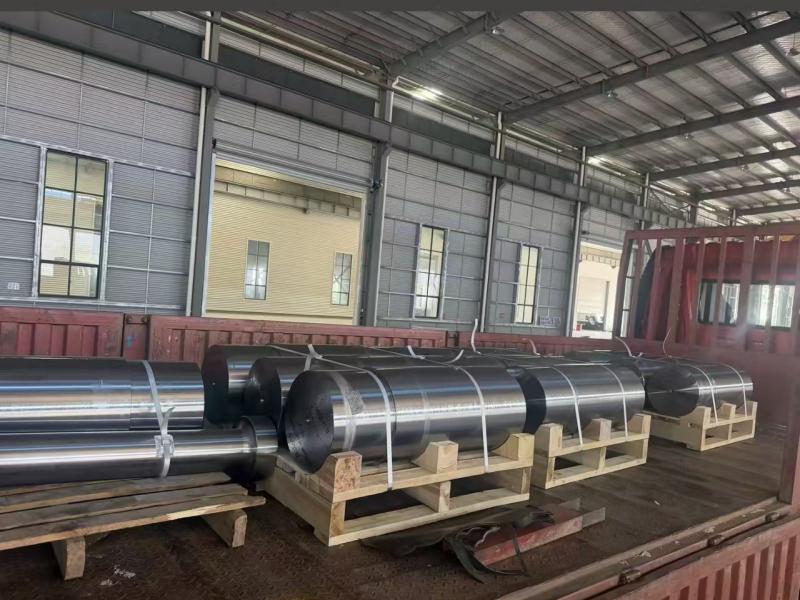
The size range is wide. A traction motor shaft may weigh a few kilograms, while a forged shaft for a large hydro set can exceed one hundred tonnes, which is why forging shops scale equipment by hammer tonnage rather than batch size.
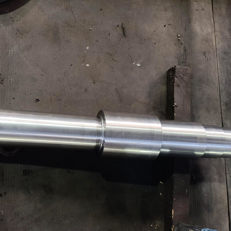 Hydroelectric Generator Shaft ForgingsLarge forged shafts for hydro turbine generator sets, available in 35CrMo, 45#, or 16Mn and weighing up to 10000 kg. The article notes forged shafts can exceed one hundred tonnes, so this product shows how forging shops scale for such sizes.View Product →
Why Forging Wins on Grain Flow and Internal Soundness
Three mechanisms give a forged rotor shaft its advantage. First, hot working refines the as-cast grain structure and closes the shrinkage porosity and micro voids that are normal in an ingot, provided the forge applies a sufficient reduction ratio, commonly at least three to one for critical shafts. Second, the elongated grains form a flow pattern that follows the contour of the shaft, so stress concentrates less at steps, fillets, and keyways. Third, forging distributes alloying elements and inclusions more evenly, which stabilizes heat treatment results across the whole cross section.
Relative fatigue strength by manufacturing route, forged shaft indexed to 100
The chart indexes the fatigue strength of a quenched and tempered forged shaft at 100 and compares the other common production routes. Machined bar stock performs respectably because rolled bar already carries some directional working, but every machining cut at a shoulder or groove interrupts the grain exactly where rotors are most highly stressed. Castings rank lower mainly because of internal shrinkage and a coarser grain structure rather than any weakness of the alloy itself. Sand castings trail investment castings because slower cooling gives less control over defects. For a part facing millions of bending and torsion cycles, the forged route is normally the default choice. Surface condition and heat treatment still shift these numbers, so read the chart as a ranking of routes rather than a guarantee for one specific design.
How a Forged Rotor Shaft Is Made Step by Step
The route below describes a typical alloy steel shaft, and every stage exists to remove a specific risk.
- Material selection: clean steel is bought to a defined grade and melt practice, with heat number traceability carried through to the test report.
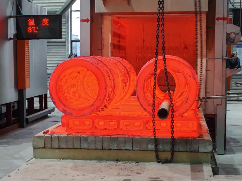
- Furnace heating: the ingot or billet is soaked at roughly 1150 to 1250 degrees Celsius so the whole section reaches forging temperature evenly.
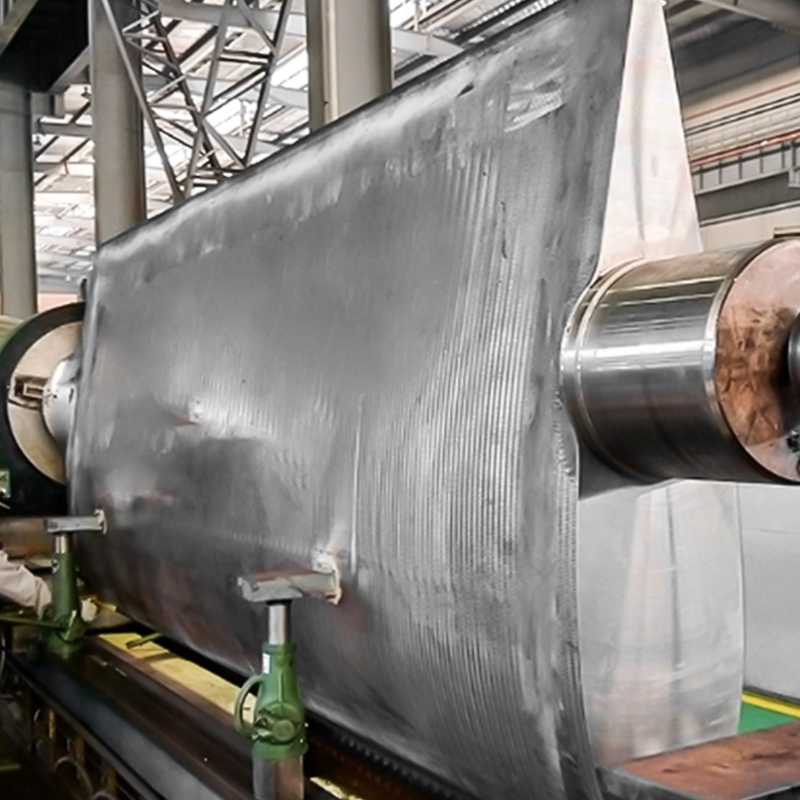
- Hot forging: the stock is drawn out and upset under the hammer or press until the planned reduction is reached, and hollow shafts are punched and expanded over a mandrel.
- Heat treatment: normalizing or quenching and tempering sets the strength and toughness combination, verified on test coupons cut from the same heat.
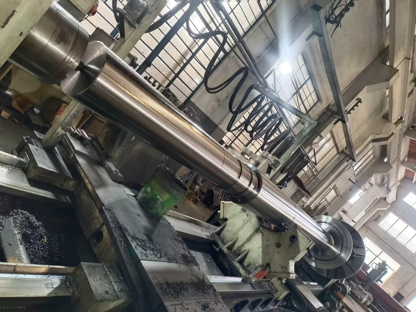
- Rough machining: the shaft is turned to a near net profile while leaving allowance for inspection and final fitting.
- Inspection: ultrasonic testing scans the full body for internal discontinuities, and magnetic particle testing checks machined surfaces for cracks.
- Finish machining and grinding: journals, seal seats, and coupling faces are ground to final tolerance, commonly an IT6 grade on bearing fits.
- Balancing and documentation: the rotor is balanced to the agreed grade and shipped with complete test and dimensional records.
Heat Treatment and Inspection
Heat treatment is where the shaft earns its mechanical properties, and it deserves the same attention as the forging itself. Normalizing suits smaller sections and simpler stress cases, while quenching and tempering delivers the deep, uniform strength that large diameter shafts need. If you want a plain language refresher, our overview of metal heat treatment basics walks through normalizing, quenching, tempering, and annealing in practical terms.
Why Machining Allowance Grows With Shaft Diameter
Typical machining allowance on diameter for open die shaft forgings, in mm
The chart shows typical allowance on diameter for an open die shaft forging before finish machining. Allowance grows with diameter because open die tolerances scale with size, thicker sections distort more during quenching and tempering, and the ultrasonic scan needs a clean machined surface to read reliably. Every millimetre of allowance is metal that must later be cut away, so an oversized forging quietly inflates machining hours and lead time. A supplier who forges close to net shape while still leaving enough stock for inspection and heat treatment movement is usually the more economical choice even at a slightly higher forging price. Buyers should pin the allowance figure down during drawing review rather than discovering it inside a quotation.
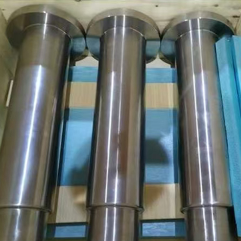 Deep Hole Spindle ForgingsFlanged shafts with a deep bore for feed machinery transmission, made in C45 with diameters of 420–755 mm. The surrounding discussion of machining allowance and near-net-shape forging makes the bore and flange geometry here especially relevant.View Product →
Forged Shaft, Casting, or Machined Bar Stock
Forging is not automatically the right answer for every rotor, and an honest comparison helps buyers spend money where it counts. The radar chart below rates the three common routes on six factors that matter for rotating parts.
Route comparison for rotor shafts across six selection factors
Forged and heat treated Machined from rolled bar Casting
Each axis runs from 0 at the center to 10 at the outer ring, and the three polygons show how the common routes differ. Forged shafts lead on fatigue strength, toughness, and internal soundness, which is precisely the profile a highly stressed rotor needs. Castings score best on design flexibility because they reach complex internal passages and external shapes that a hammer cannot produce, and they stay economical at moderate volumes. Machined bar stock wins on lead time and cost efficiency for small diameter shafts, since the material sits on the shelf and no forging or tooling step is required. The weaknesses appear at the extremes: bar stock cannot deliver a large diameter or a worked core, and castings struggle in high cycle fatigue service. A pragmatic rule is to forge when bending and torsional stresses are high, to cast when geometry dominates, and to machine from bar when diameter and duty are modest.
What Buyers Should Specify Before Ordering
Most disputes over forged shafts trace back to specifications that were never written down. The table below collects the order details that decide cost, lead time, and service life.
| Specification | Why it matters | Practical guidance |
|---|---|---|
| Steel grade and melt practice | Sets the ceiling for strength, toughness, and machinability | Alloy steels such as 42CrMo4 or 34CrNiMo6 suit most power and industrial rotors, while stainless grades serve corrosive duty |
| Mechanical property limits | Defines acceptance for yield, tensile, elongation, and impact energy | State the values and the test direction, since tangential and longitudinal results differ |
| Heat treatment route | Controls strength depth across the section | Quench and temper for large diameters, and ask for the actual tempering temperature in the report |
| Ultrasonic acceptance class | Prevents internal defect disputes after machining | Agree the class and the scan timing before production starts |
| Machining allowance and fits | Determines finishing cost and bearing fit quality | Confirm allowances at drawing review and specify ground journals where fits are critical |
| Balancing grade | Governs vibration and bearing life at speed | High speed rotors usually need a tighter grade than general industrial machines |
Quantity deserves the same scrutiny as chemistry, because fixed costs dominate small orders. The curve below shows how the unit price of a forged shaft typically behaves as batch size grows.
Indicative unit cost index for forged shaft orders versus quantity
The curve is an indicative cost index for a batch of forged rotor shafts plotted against order quantity, with the single piece set at 100. The first piece carries setup, tooling preparation, test coupons, and full documentation, which is why it dominates the price. By ten pieces those fixed costs are spread across the batch and the index falls to roughly 62. Buyers can use this behavior in two ways: consolidate duplicate spares into one release order to reach a better price break, or accept a higher unit price for a single critical shaft where holding inventory would cost more than the discount. It also explains why quotations for one piece and for twenty pieces are never directly comparable, and why it is worth asking a supplier to price two or three quantity points before committing.
Working With an Integrated Forging Partner
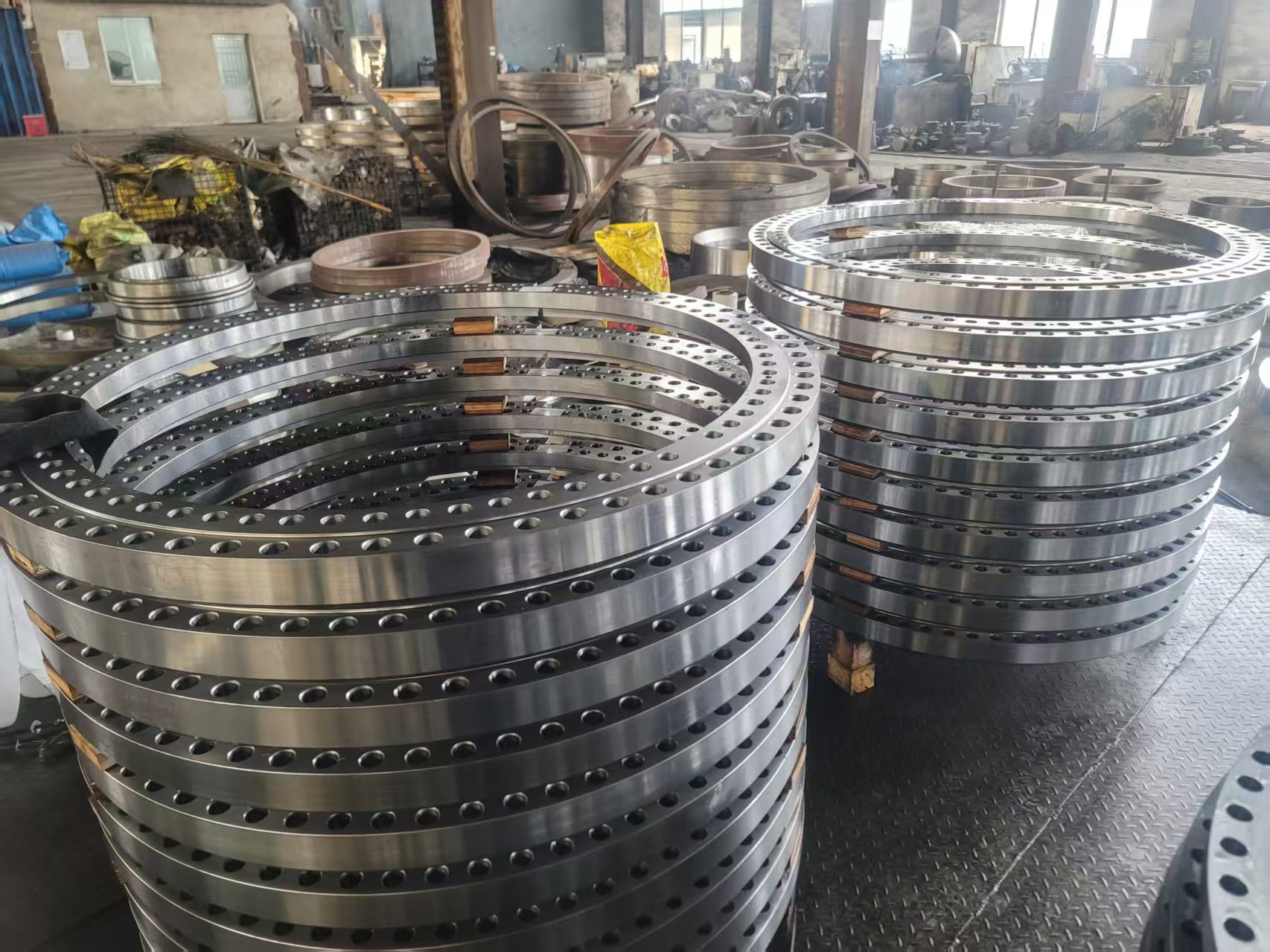
The specification decides half of the outcome, and the supplier decides the other half. Look for a shop that keeps forging, heat treatment, inspection, and machining under one roof, because every handover between separate vendors adds transport, queue time, and a place where responsibility gets blurred. Our plant in Jiangsu runs 3, 5, and 15 tonne electro-hydraulic hammers, 1 m and 1.5 m ring rolling machines, gas fired heating furnaces, quench tanks, induction hardening equipment, and machining centers on the same 55 acre site, so a shaft can move from billet to balanced, inspected component without leaving our control.
That integration matters most for shafts outside catalog sizes. Where a rotor needs an unusual diameter, a flanged end, or a bored center, a supplier that routinely handles non-standard customized forgings can quote from the drawing instead of forcing a redesign. Gear shafts, generator shafts, and deep hole spindles all follow the same principle: define the duty, choose the manufacturing route, and verify every stage with records rather than promises.
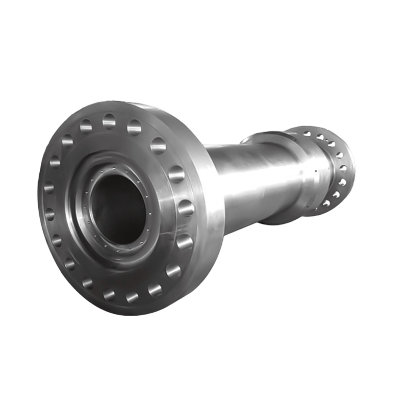 Gear Shaft ForgingsHigh-strength forged gear shafts in 22Cr-13Ni-5Mn-N or 316, sized 30 mm to 3200 mm in diameter for port cranes and deck machinery. The article highlights non-standard forgings quoted from drawings, matching this product's customizable equipment adaptation.View Product →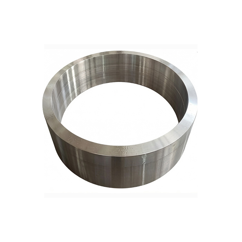
Message Us Right Now!
-
Mobile Terminal
-
Quick Links
Products About Us Equipment & Capacity Quality News Contact Us -
Product Category
Power‑Generation Forgings Ship and Port Machinery Forgings Mining and Metallurgy Forgings Food and Feed Machinery Forgings Welding Fabrication Petrochemical Industry Forgings CUSTOMIZED MADE FORGING PARTS -
Contact Us
Mob.: +86-173 7218 0878 Tel.: +86-515-8389 0396 E-mail: ivy.zhai@aceprocess.cn Add.: No.21 Jinfeng Road, Economic Development Park, Dafeng District, Yancheng City, Jiangsu, China
Copyright © 2025 Yancheng ACE Machinery Co., Ltd. All Rights Reserved.
China open die forgings manufacturer
custom precision forgings supplier
