

 English
 中文简体
中文简体

Industry News


Industry News
What is the function of a flanged wheel?
2026-08-28
The core function of a Flanged Wheel is to resist the lateral, sideways forces that build up as the wheel rolls, so the wheel stays correctly positioned on its rail or track instead of sliding off under load. In normal operation the flange rarely makes contact at all, since the tapered tread profile of the wheel does most of the steering work by self centering the wheel through gentle rolling radius differences, but the moment lateral force builds beyond what the tread profile can correct, the flange engages the rail's edge and physically blocks further sideways movement. Railway engineering research quantifies exactly how much lateral force the flange can safely resist before this protective function fails, showing that once the ratio of lateral to vertical force at the contact point approaches a value of 1.0, the wheel flange begins to climb the rail rather than hold position, which is the mechanical definition of derailment by flange mounting.
Content
- 1 Self Centering Steering Comes First, the Flange Is the Backup
- 2 The Safety Limit: How Much Lateral Force a Flange Can Resist
- 3 Load Bearing and Contact Stress Management
- 4 The Flange's Role in Curved Track and Crane Rail Systems
- 5 Structural and Torque Transmission Function in Gearbox Assemblies
- 6 How Wheel and Flange Geometry Support These Functions
- 7 Functional Checklist for Specifying a Flanged Wheel
Self Centering Steering Comes First, the Flange Is the Backup
A common misconception is that the flange is doing the steering work at all times. In reality, most flanged wheels used on rail systems are shaped with a slightly conical or tapered tread rather than a flat cylindrical one, which means a wheelset naturally rolls toward the center of the track without flange contact under normal straight line running. This tread taper creates a small difference in effective rolling radius as the wheel drifts off center, generating a self correcting steering force. The flange's primary function only activates when this self centering effect is not enough, such as when the vehicle enters a curve, hits a track irregularity, or experiences a sudden lateral disturbance, at which point the flange makes contact with the rail's gauge face and takes over the steering and containment function directly.
The Safety Limit: How Much Lateral Force a Flange Can Resist
Railway engineering research on wheel rail contact forces defines the flange's protective function using what is known as Nadal's formula, which relates the ratio of lateral force (Y) to vertical force (Q) at the wheel rail contact point to the flange angle and the coefficient of friction between wheel and rail. Using a friction coefficient of 0.27 and a flange angle of 60 degrees, published research shows the Y over Q ratio reaches its limiting value of approximately 0.997, effectively 1.0, beyond which the flange can no longer hold its position and instead begins to mount, or climb, the rail. This single ratio is the practical engineering definition of how much sideways load a flanged wheel's guidance function can safely absorb before failing, and it is why flange angle, wheel diameter and friction management at the wheel rail interface are treated as safety critical design parameters rather than dimensional preferences.
Why Duration of Overload Also Matters
Research on force measurement in dynamic rail conditions notes that exceeding the critical Y over Q ratio briefly does not automatically cause derailment, since the duration for which the ratio can exceed 1 before an actual flange climb occurs is also a factor engineers account for in design and monitoring. This is why on loading and off loading events of more than 50 percent of a wheel's normal vertical force are treated as a design concern on major rail networks, even when they are momentary, since repeated brief overloads can still push the lateral to vertical ratio into an unsafe range during the exact moment they occur.
Load Bearing and Contact Stress Management
Beyond steering, a flanged wheel's tread performs a second essential function: distributing the vehicle or machine's weight across a very small contact area without generating excessive stress that would damage the wheel or rail surface. Engineering analysis of wheel rail contact mechanics describes this contact area using Hertzian contact theory, where the normal stress across the small elliptical contact patch is calculated based on the wheel and rail profile geometry at that specific point of contact. On straight track or very high radius curves, contact occurs on the tread's central running band, which produces the lowest stress and lowest lateral force condition, while contact shifts toward the flange root or flange face itself as curving forces increase, concentrating stress in a smaller area exactly where the wheel needs to resist the greatest sideways load.
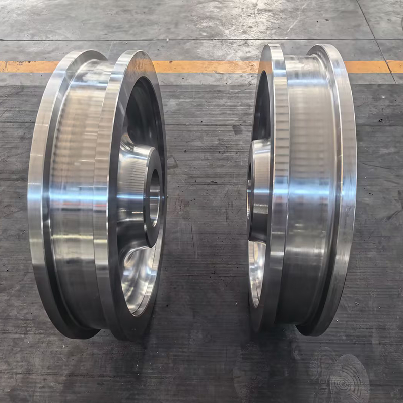
The Flange's Role in Curved Track and Crane Rail Systems
The steering function of a flange becomes most active during curving motion, whether on a railway curve or a crane bridge negotiating a rail joint or slight misalignment. Engineering guidance on wheel rail interface behavior explains that during curving, the wheel tread makes contact at the top of the outer, or high, rail while the flange applies curving and steering lateral force at the rail's gauge face, with no flange contact typically occurring on the inner, or low, rail at all. This asymmetric contact pattern means the flange functions almost exclusively as an active steering component on the outer wheel of a curve, while the inner wheel relies mostly on tread contact and vertical load to maintain its path, which is why flange wear and lubrication practices are typically focused on the high rail side of curved track sections.
Structural and Torque Transmission Function in Gearbox Assemblies
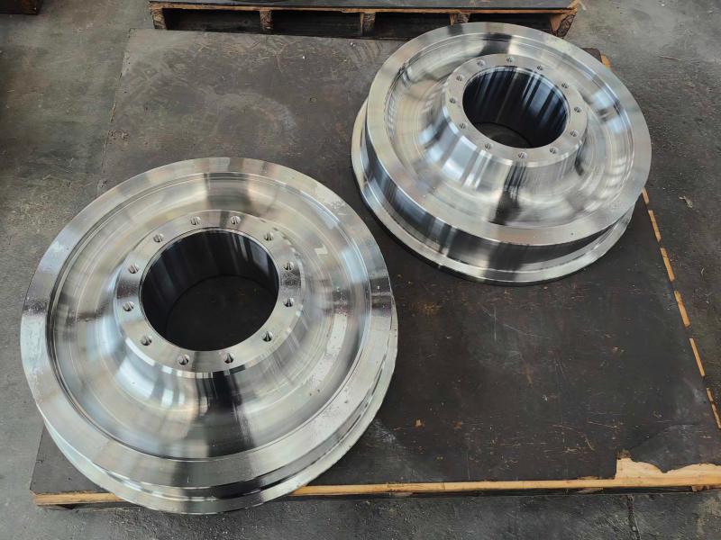
In heavy machinery contexts such as wind turbine gearboxes and crane drivetrains, a forged flanged wheel takes on a related but distinct function: rather than steering along a rail, its flange acts as a precision mounting and load transfer interface between rotating components. Patent documentation on modular gearbox design describes flange connections specifically as ring shaped structural elements that transmit torque and structural load between adjoining gear stage modules, with fastening components securing each side of the flange under significant operating stress. In this application, the flange's function shifts from lateral guidance to structural rigidity and precise alignment, ensuring torque is transmitted smoothly between rotating shafts without introducing misalignment or vibration into the drivetrain.
How Wheel and Flange Geometry Support These Functions
| Design Parameter | Functional Role |
| Flange Angle | Determines the lateral force threshold before flange climb occurs, per Nadal's formula |
| Flange Height | Sets the safety margin against flange override under peak lateral load |
| Tread Taper or Profile | Provides self centering steering before flange contact is needed |
| Wheel Diameter | Affects contact stress distribution and load per wheel capacity |
Functional Checklist for Specifying a Flanged Wheel
- Confirm the flange angle and height provide adequate margin against the maximum expected lateral to vertical force ratio
- Match tread profile design to the operating track curvature and speed range of the application
- Specify forged construction with appropriate heat treatment where the wheel must resist sustained flange contact stress
- For gearbox and structural flange applications, confirm the flange interface meets required torque transmission and alignment tolerances
- Plan lubrication or friction management at the flange to rail interface where curving or high lateral load conditions are expected
The function of a flanged wheel is fundamentally about force management: the tread and its taper handle everyday steering through self centering rolling behavior, while the flange stands ready as a protective backup that engages only when lateral force threatens to push the wheel off its intended path, engineered to hold firm right up to the point defined by Nadal's roughly 1.0 lateral to vertical force limit. In heavier structural and drivetrain contexts, that same flange geometry is repurposed to transmit torque and maintain precise alignment between rotating components instead of guiding a wheel along a rail. A properly engineered forged Flanged Wheel is built to perform whichever of these functions its application demands, reliably and without failure, across millions of load cycles.
Message Us Right Now!
-
Mobile Terminal
-
Quick Links
Products About Us Equipment & Capacity Quality News Contact Us -
Product Category
Power‑Generation Forgings OEM Machined Forgings CUSTOMIZED MADE FORGING PARTS Ship and Port Machinery Forgings Mining and Metallurgy Forgings Food and Feed Machinery Forgings Welding Fabrication Petrochemical Industry Forgings -
Contact Us
Mob.: +86-173 7218 0878 Tel.: +86-515-8389 0396 E-mail: ivy.zhai@aceprocess.cn Add.: No.21 Jinfeng Road, Economic Development Park, Dafeng District, Yancheng City, Jiangsu, China
Copyright © 2025 Yancheng ACE Machinery Co., Ltd. All Rights Reserved.
China open die forgings manufacturer
custom precision forgings supplier
