

 English
 中文简体
中文简体

Industry News
Home / News / Industry News / Custom Steel Rolled Forgings for Oil and Gas: A Buyer and Engineering Guide
 Home / News / Industry News / Custom Steel Rolled Forgings for Oil and Gas: A Buyer and Engineering Guide
Industry News
Custom Steel Rolled Forgings for Oil and Gas: A Buyer and Engineering Guide
2026-09-24
A valve cover forging reaches final inspection with a 14 mm wall thickness spread across a 90 mm section, the assembled body fails a hydrostatic test at the flange transition, and the schedule slips six weeks. The drawing was correct, so the rolling plan was not. The preform was too small for the mandrel, the wall was finished in two light passes, and the centerline never consolidated.
The short version for anyone writing a purchase order: treat the rolling route, the reduction ratio, and the inspection standard as one package. A ring rolled to at least a 3 to 1 reduction and verified by ultrasonic testing behaves predictably in pressure service. A neat, well machined ring cut from plate with no reduction record does not.
Content
- 1 Why the Rolling Route Decides Pressure Performance
- 2 From Billet to Finished Ring: The Custom Rolling Sequence
- 3 Tolerances, Reduction Ratios, and the Numbers That Get Audited
- 4 Matching the Rolling Plan to the Component
- 5 Inspection, Documentation, and Stainless Grades
- 6 When a Rolled Ring Is Right and When It Is Not
Why the Rolling Route Decides Pressure Performance
Rolling does more than shape a ring. When a heated preform is compressed between a driven main roll and a mandrel, the wall thins and the circumference grows, so the metal fibers are dragged around the ring instead of being sliced across it. In a casing head or a blowout preventer body, the governing stress is hoop stress, and circumferential fibers sit directly in the load path. A ring cut from rolled plate carries fibers through the thickness, exposing end grain on the bore and the outside diameter, where ultrasonic energy scatters unpredictably.
Consolidation is the second effect. Rolling a thick wall down to size closes internal porosity only when the reduction is large enough to reach the centerline, which is why most oil and gas specifications set a minimum 3 to 1 reduction from the starting cross section and experienced buyers ask for 4 to 1 or better on pressure retaining walls.
Figure 1. Circumferential grain flow continuity index by production route, scored out of 100
The index scores circumferential grain flow continuity out of 100, where a perfect score means the fibers run unbroken around the entire ring. A seamless rolled ring scores highest because the mandrel squeezes the wall in one continuous pass and no fiber is cut. Open die forging followed by boring keeps fibers continuous but usually leaves more machining stock and a rougher bore. A ring cut from plate loses ground exactly at the inner and outer surfaces, where the cut crosses the fiber direction. Castings sit lowest because shrinkage porosity can mimic forging indications on an ultrasonic screen while behaving very differently under pressure.
From Billet to Finished Ring: The Custom Rolling Sequence
Custom rolling is a sequence, and a step skipped at the furnace shows up at final inspection.
- Billet selection with verified chemistry, heat number, and ultrasonic examination of the starting stock.
- Cutting and controlled heating in a gas furnace until the section is uniformly through the austenitizing range.
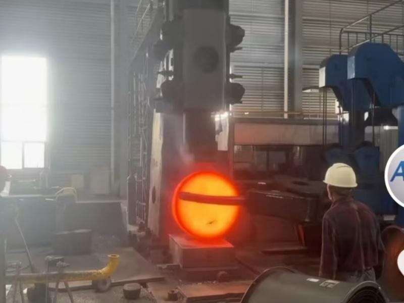
- Upsetting and drawing on an electro hydraulic hammer to break down the cast structure and build a preform.
- Punching the preform, then expanding it over a mandrel.
- Ring rolling on a vertical mill until wall thickness and height match the rolling plan.
- Heat treatment, normally normalize, austenitize, quench, and temper, to reach the specified strength and toughness.
- Rough machining, ultrasonic testing, finish machining, and final dimensional and hardness verification.
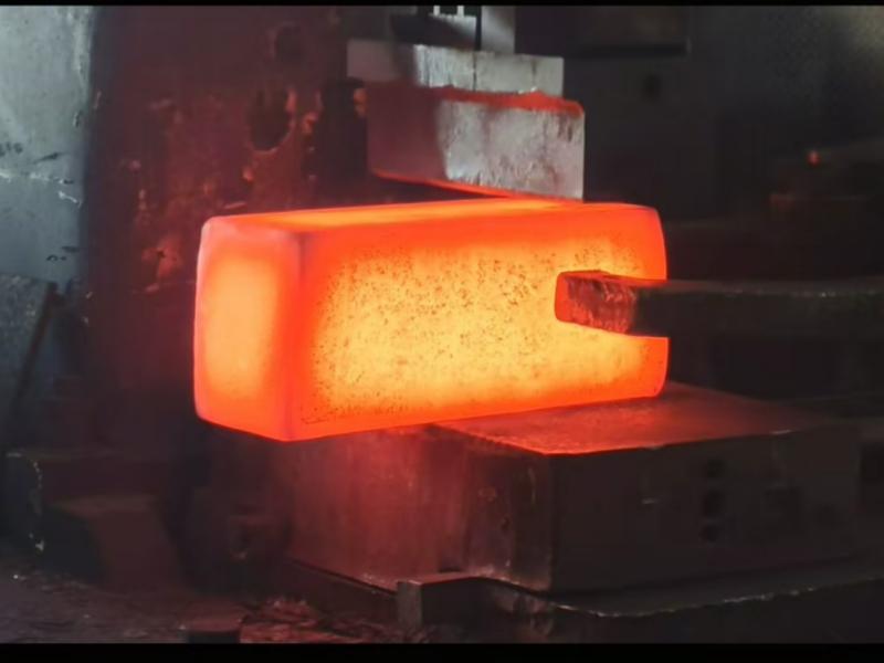
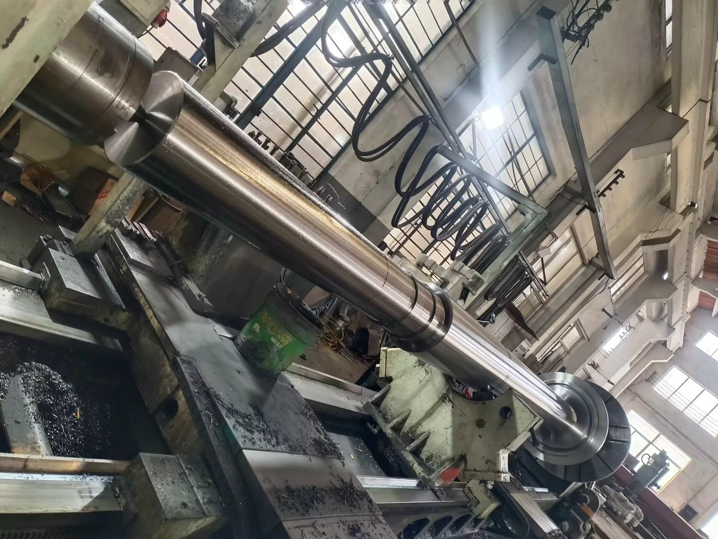
Equipment sets the practical envelope. Electro hydraulic hammers from 3 t to 15 t and vertical ring rolling machines of 1 m and 1.5 m working diameter cover a wide band of ring sizes, and interchangeable tooling is what makes custom geometry possible instead of a catalogue compromise. Keeping forging, heat treatment, and machining under one quality system also removes the argument about who damaged the material between operations, which is a familiar dispute when a ring travels between three vendors. An integrated chain such as ACE Group holds one heat number traceable from billet to finished part.
Tolerances, Reduction Ratios, and the Numbers That Get Audited
Specification writing is where the risk is either removed or created. The reduction ratio, the wall thickness tolerance, and the ultrasonic acceptance level do most of the work, and no amount of machining skill recovers a ring that was rolled too lightly.
| Parameter | Typical working range | Why it decides acceptance |
|---|---|---|
| Ring outer diameter | 300 mm to 2,500 mm | Sets the mill and mandrel combination, and therefore the achievable wall tolerance |
| Wall thickness | 40 mm to 400 mm | Thick walls need longer soak times and a higher reduction ratio to consolidate |
| Ring height | 50 mm to 600 mm | A height to wall ratio above roughly 3 to 1 makes the ring prone to dishing during rolling |
| Forging reduction ratio | 3 to 1 minimum, 4 to 1 preferred | Below 3 to 1, internal porosity can survive rolling and appear as ultrasonic indications |
| Wall tolerance after rolling | plus or minus 8 percent of nominal | Machining stock has to absorb the spread, or the finished wall falls under minimum |
| Heat treatment | Normalize, quench, and temper | Hardness spread across the section is one of the first items a field inspector checks |
| Ultrasonic testing | ASTM A388, flat bottom hole size set by the purchase order | The acceptance level decides whether the ring is a pressure part or scrap |
Reduction ratio is the item buyers most often leave blank, and it is the one that predicts internal soundness.
Figure 2. Reduction ratio against the share of thick wall rings rejected for internal indications
Each point shows a typical relationship between the planned reduction ratio and the share of thick wall pressure rings rejected for internal indications. The curve falls steeply between 1.5 to 1 and 3 to 1, the range where porosity and segregation can still reach the finished wall. Beyond 3 to 1 it flattens, and the remaining rejections come from hydrogen content, soaking time, or mandrel marks rather than from the reduction itself. That shape is why a 4 to 1 requirement buys confidence cheaply while pushing past 5 to 1 mostly buys cost. It also explains why a supplier who cannot state the reduction ratio for a given ring size cannot honestly guarantee internal soundness.
Matching the Rolling Plan to the Component
Casing heads, tubing spools, and wellhead bodies
These parts pair a heavy flange with a thinner neck, so one ring has to balance two very different wall sections. Walls of 60 mm to 150 mm are normal, and the flange is often thickened by a separate upset or added by welding. The risk is a neck that looks adequate on the drawing but is too thin at the preform stage to consolidate.
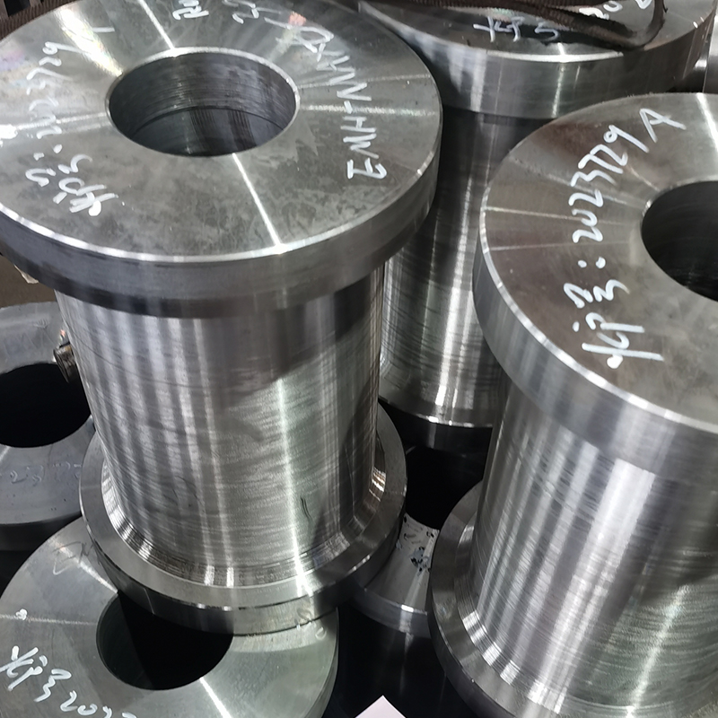 Casing Head ForgingsThe casing head is a core component of wellhead equipment, primarily used to connect casing strings of different specifications downhole. It also enables wellhead pres...View Product →
Blowout preventers and high pressure bodies
BOP bodies and fracturing heads are the heaviest rings in the family, with walls above 200 mm and low temperature impact requirements. Thick sections soak slowly and the quench must reach the centerline without cracking the surface, so the heat treatment recipe matters as much as the rolling pass. Reduction ratios of 4 to 1 or 5 to 1 are normal here.
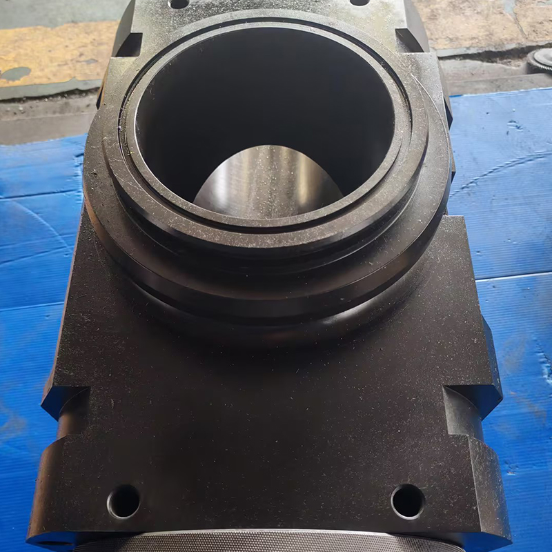 Blowout Preventer Forgings1. Applications They are widely used in conventional onshore oil and gas drilling operations. Whether during the drilling of exploration wells or production wells, whe...View Product →
Valves, chokes, and flow control parts
Valve covers, mandrel hangers, and pump housings sit at the other end of the size range, with thinner walls, tighter tolerances, and more stainless or duplex grades. Duplex material is unforgiving about temperature, so the rolling and heat treatment windows are narrow and heat traceability is checked closely.
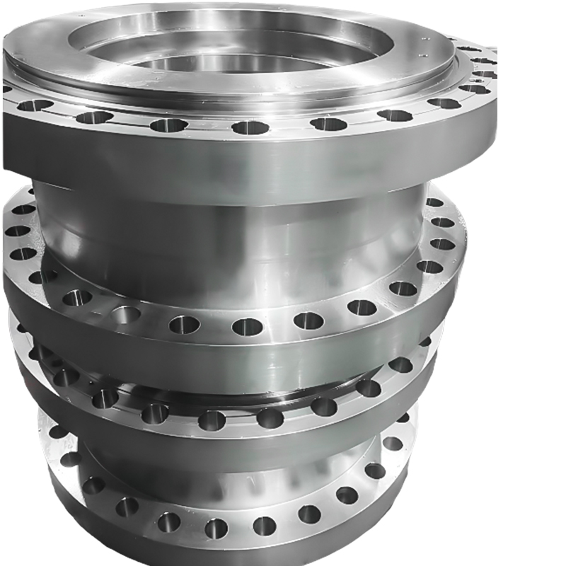 Valve Cover Forgings1. Core Structure Core Value The core structure of a three-piece ball valve consists of a "left valve body + middle valve body + right valve body" (the three parts are...View Product →
Figure 3. Typical achievable wall thickness tolerance after rolling, by ring outer diameter
4 mm
6 mm
9 mm
13 mm
17 mm
600 mm1000 mm1500 mm2000 mm2500 mm
Wall thickness tolerance is not one number, because the mandrel and main roll deflect more as the ring grows. The columns show typical achievable bands after rolling and before machining, from a few millimetres on a 600 mm ring to a much wider allowance on a 2500 mm ring. Buyers who ignore that relationship end up specifying a tolerance that forces unnecessary machining stock on small rings and makes large rings almost impossible to produce. The practical route is to state the finished wall requirement and let the forge allocate stock on top of it. That also makes supplier quotations comparable, because every quote is priced against the same finished geometry.
Inspection, Documentation, and Stainless Grades
Inspection documentation is what makes a rolled ring verifiable. Ultrasonic testing to ASTM A388 with a flat bottom hole size agreed on the purchase order, magnetic particle inspection of machined surfaces, and a hardness survey across the wall catch most problems before shipment. Certificates to EN 10204 3.1, traceable heat numbers, and Charpy results from the same heat lot are the records an operator may ask for years later.
Stainless grades behave differently under the hammer. SS316L and similar austenitic steels work harden locally instead of hardening uniformly, and they are prone to hot cracking when the forging temperature window is missed. SS420 wear rings need controlled cooling to reach hardness without cracking. Our notes on how stainless steel forgings are produced cover that trade off in more detail.
When a Rolled Ring Is Right and When It Is Not
Rolled rings are not automatically the right answer. For a thin wall ring under about 40 mm with a large diameter and light duty, a ring cut from plate or from seamless pipe can be cheaper and fast enough.
Figure 4. Custom rolled ring against plate cut ring, scored out of ten across six sourcing criteria
The comparison scores each route out of ten across six criteria, so the shape of the polygon matters more than any single value. The rolled ring route pulls outward at the top, where pressure containment and inspection reliability sit, because circumferential grain flow and a documented reduction ratio support both. The plate cut route is stronger on the left, where material utilization and low volume cost are scored, since a plate can be nested to produce several rings with little scrap. Dimensional repeatability is closer than most buyers expect, because a machined plate ring is accurate even when its internal quality is not. The rule that follows is straightforward: if the part contains pressure or sees cyclic loading, pay for the rolled ring, and if it is a spacer or a low duty flange, the plate route is defensible.
A rolled ring is only as good as the plan behind it. Put the reduction ratio, the rolling sequence, the wall tolerance, and the ultrasonic acceptance level on the purchase order, ask for the heat treatment curve, and require the heat number on every certificate. Do that, and the wall spread, the failed hydrostatic test, and the six week slip stop being a matter of luck.
Message Us Right Now!
-
Mobile Terminal
-
Quick Links
Products About Us Equipment & Capacity Quality News Contact Us -
Product Category
Power‑Generation Forgings OEM Machined Forgings CUSTOMIZED MADE FORGING PARTS Ship and Port Machinery Forgings Mining and Metallurgy Forgings Food and Feed Machinery Forgings Welding Fabrication Petrochemical Industry Forgings -
Contact Us
Mob.: +86-173 7218 0878 Tel.: +86-515-8389 0396 E-mail: ivy.zhai@aceprocess.cn Add.: No.21 Jinfeng Road, Economic Development Park, Dafeng District, Yancheng City, Jiangsu, China
Copyright © 2025 Yancheng ACE Machinery Co., Ltd. All Rights Reserved.
China open die forgings manufacturer
custom precision forgings supplier
