

 English
 中文简体
中文简体

Industry News
Home / News / Industry News / Open Die Forgings Guide: Process, Tolerances, Cost, and Lead Time Planning
 Home / News / Industry News / Open Die Forgings Guide: Process, Tolerances, Cost, and Lead Time Planning
Industry News
Open Die Forgings Guide: Process, Tolerances, Cost, and Lead Time Planning
2026-09-25
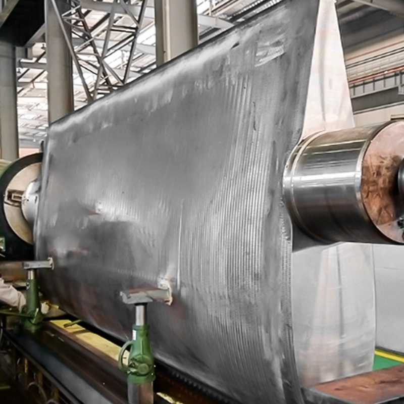
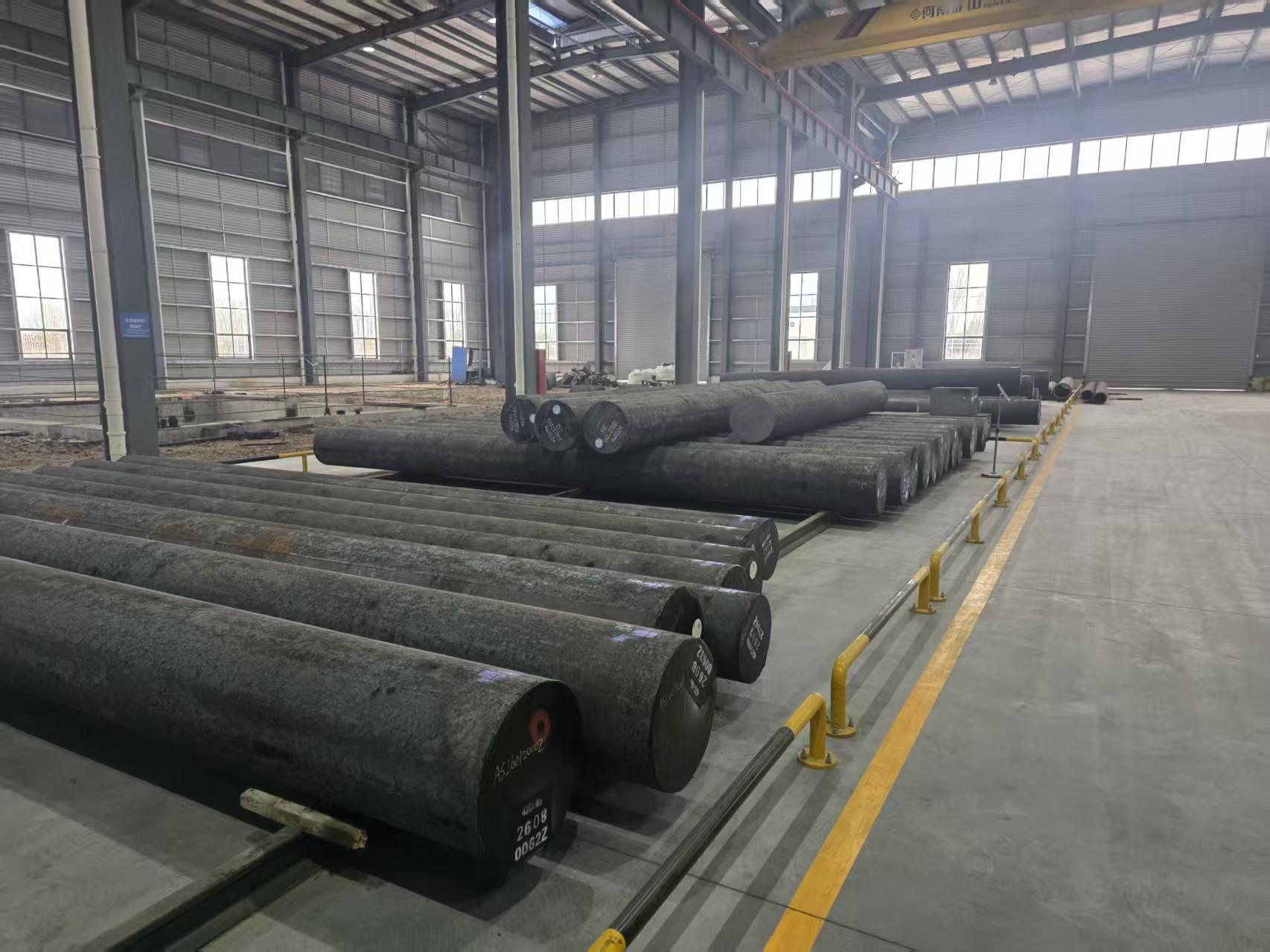
A 12 tonne cone crusher main shaft starts life as an 18 tonne ingot, and the first decision a buyer faces is not machining tolerance, it is how the metal will be shaped. Open die forgings solve that problem for most large, low volume, high integrity parts, because the hot workpiece is worked between flat or simple contoured dies that never fully enclose it. The metal is free to flow sideways, and the shape is built up over a series of passes rather than pressed in one stroke. That single characteristic decides the size range you can buy, the tooling you pay for, the tolerances that are realistic, and how much metal is left for the machine shop. This guide explains the process, compares it fairly with closed die work, and shows the numbers that matter when you release a purchase order.
Content
- 1 Open die forgings explained in practical terms
- 2 Open die forging versus closed die forging
- 3 Grain flow, reduction ratio and the properties you pay for
- 4 Materials, heat treatment and forged versus cast
- 5 Where the lead time and the cost actually go
- 6 Applications that depend on open die forgings
- 7 How to specify open die forgings in an RFQ
Open die forgings explained in practical terms
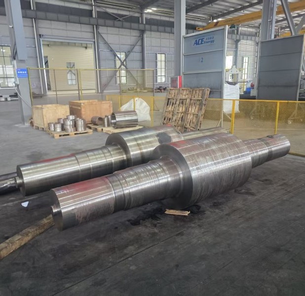
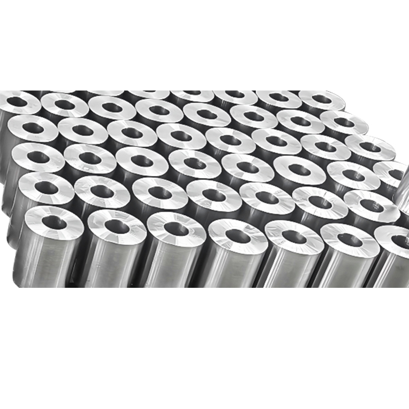
Open die forging, also called free forging, uses a hammer or press with flat, V shaped or simple contoured dies. An operator or manipulator rotates and repositions the workpiece between blows, so the final geometry is developed in stages. The core operations are upsetting, which reduces height and increases diameter, cogging or drawing, which reduces the cross section and extends the length, plus piercing, punching and ring expansion on a ring mill. Typical products are shafts, discs, rings, blocks, sleeves and stepped shafts that can reach several metres in length. Because the dies are simple and usually shared across many part numbers, tooling investment stays low, and that is the main reason open die forging remains the default route for one off and small batch heavy parts. The trade off is dimensional control: as forged tolerances are wider than closed die work, so drawings normally carry a machining allowance and the shop cuts the part to final size afterwards.
Open die forging versus closed die forging
Start with the decision rule. If the part is large, ordered in small quantities, and destined for the machine shop anyway, open die forging is almost always the cheaper route. If the part is compact, needed in tens of thousands, and used close to final shape, closed die forging wins. The table below summarises the differences that drive that choice.
| Buying factor | Open die forging | Closed die forging |
|---|---|---|
| Typical part weight | About 50 kg up to 20 tonnes and above | A few grams up to roughly 50 kg |
| Tooling | Flat or simple dies, low cost, often shared | Dedicated impression dies, high cost |
| As forged tolerance | Looser, with a generous machining allowance | Tight, close to final shape |
| Economic batch size | One piece to a few hundred | Thousands to millions |
| Shape complexity | Simple: shafts, discs, rings, blocks | Complex ribs, bosses, thin sections |
| Surface condition | Requires machining before use | Better as forged surface |
Figure 1: Capability comparison scored from 0 to 100 for the buyer
The radar chart scores both processes from 0 to 100 on five buying criteria, where a higher score always means a better outcome for the buyer. Open die forging leads on size capability, tooling cost and material range, because simple dies handle large cross sections and unusual alloys without dedicated tooling. Closed die forging takes the precision and volume axes, since impression dies control the shape in a single stroke and the tooling cost is spread over very large batches. The two outlines cross in the middle, and that crossover is the practical reason many plants use both routes, closed die for compact high run parts and open die for large shafts, rings and discs. As a rough purchasing rule, a part heavier than about 500 kg or wider than roughly 600 mm almost always lands on the open die side of that crossover. The scores are relative indicators rather than specifications, so confirm the real limits against a specific forge shop's equipment before releasing a drawing.
Grain flow, reduction ratio and the properties you pay for
Forging changes more than geometry. It breaks down the cast structure of the ingot, closes internal porosity and aligns inclusions along the direction of metal flow, which is why a forged shaft outperforms a cast or simply machined equivalent in fatigue and impact. The key number is the reduction ratio, calculated as the starting cross sectional area divided by the finished cross sectional area. Power, offshore and pressure equipment specifications commonly demand a minimum of 3:1, and demanding applications ask for 4:1 or more. The useful question is where extra reduction stops paying for itself.
Figure 2: Relative properties against forging reduction ratio, cast baseline 100
The line chart plots relative impact toughness and tensile strength against forging reduction ratio, with an as cast baseline of 100. Both curves climb steeply between 1:1 and 3:1, the range where porosity is closed and the coarse cast structure is replaced by a finer, more uniform grain. Between 3:1 and 4:1 the improvement continues but at a much slower rate, and past 5:1 the lines are almost flat. In commercial terms, paying for a 5:1 reduction on a part that will be machined down to a fraction of its cross section adds cost without a measurable property gain. The two curves also show why reduction ratio should be specified together with grain flow direction, because longitudinal properties improve faster than transverse ones. A practical approach is to set the minimum ratio from the fatigue or pressure requirement in the design, then let the forge shop select the pass schedule that meets it.
Materials, heat treatment and forged versus cast
Alloy steels such as 42CrMo4 and 34CrNiMo6 cover the majority of shafts, gears and rings, and stainless grades are chosen where corrosion or hygiene matters. In food, feed, pump and marine service, SS316L is common for impellers and wipers, while SS420 is used for wear rings and other abrasion resistant parts. Stainless work is less forgiving in the furnace, so heating and cooling must be controlled to avoid sensitisation and unwanted phase formation, and the same discipline described in this guide to forging stainless steel forgings also determines how much clean up machining is needed afterwards. Heat treatment after forging, whether normalising, quenching and tempering or solution annealing, is what finally delivers the mechanical properties, so the specification should state the condition, the sampling position and the test standard rather than a hardness number alone.
Figure 3: Property index of forged parts versus as cast parts of the same alloy
The bar chart shows a relative index of properties for open die forged parts against as cast parts of the same alloy, with the casting set at 100. Fatigue strength and internal soundness show the largest gains, which is exactly what you would expect once porosity is closed and grain flow is aligned with the load path. Impact toughness and tensile strength also improve, though by a smaller margin. The reason the fatigue and soundness bars are so much longer is that castings retain shrinkage porosity and coarse dendrites that act as crack initiation sites under cyclic loading. It is worth noting that the index describes typical behaviour rather than a guaranteed ratio for a specific grade, and the advantage narrows when a casting receives a full heat treatment and thorough non-destructive examination. Use the comparison to justify the process route in a design review, then confirm real properties with test results from the forging supplier.
Where the lead time and the cost actually go
On a large open die forged shaft, tooling is rarely the biggest cost item because the dies are simple and often already in the shop. Material weight, the number of forging passes, heat treatment cycles, machining allowance and inspection requirements drive the price. Lead time behaves the same way: most of the weeks are spent before and after the hammer, not under it. The chart below shows a typical breakdown for a shaft in the 2 to 5 tonne range.
Figure 4: Typical nine week lead time split for a large open die forged shaft
The column chart splits a typical nine week lead time into five stages, and the pattern often surprises buyers who expect forging to be the bottleneck. Tooling and fixture preparation takes about two weeks, heating and forging only around one and a half, and heat treatment another two because a large section needs controlled heating and cooling rates. Rough machining consumes the largest single block at two and a half weeks, while final inspection, ultrasonic testing and documentation take about one week. The planning message is straightforward: money and time are saved by reducing machining allowance and simplifying the heat treatment route, not by pressing the forge shop for a faster hammer. When a project schedule is tight, book heat treatment furnace capacity and machining slots early, because those two stages are the least flexible. Also confirm whether the quoted lead time starts from drawing approval or from material arrival, since that difference alone can move a delivery date by weeks.
Applications that depend on open die forgings
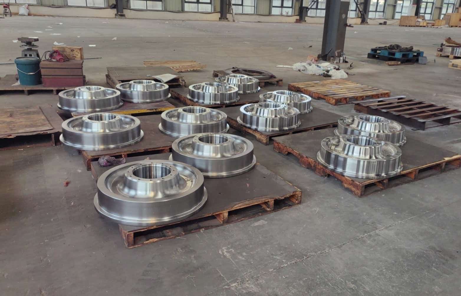
Power generation is the largest consumer of heavy open die forgings. Wind turbine gearboxes in the 3 MW to 10 MW class use forged planet carriers, planet gears, sun gears and ring gears, hydro plants use guide vanes and generator shafts, and nuclear stations use conventional island parts, piping nozzles and tube sheets. In each case the part is safety related, inspected by ultrasonic testing and expected to survive decades of cyclic loading.
 Wind Turbine 3MW-10MW Planet Carrier ForgingsWind turbine planet carrier forgings chinese manufacturerView Product →
Marine and port machinery relies on forged shafting and steering gear. Propeller shafts, intermediate shafts, stern shafts, rudder stocks and rudder pintles are produced by open die forging because they combine a large cross section with a fatigue critical duty cycle, and because classification societies require documented grain flow and test results.
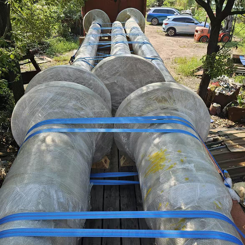 Propeller Shaft ForgingsAs a core forged component, the propeller shaft (specifically referring to marine propeller shafts) serves as a key forged part for propellers, primarily utilized in c...View Product →
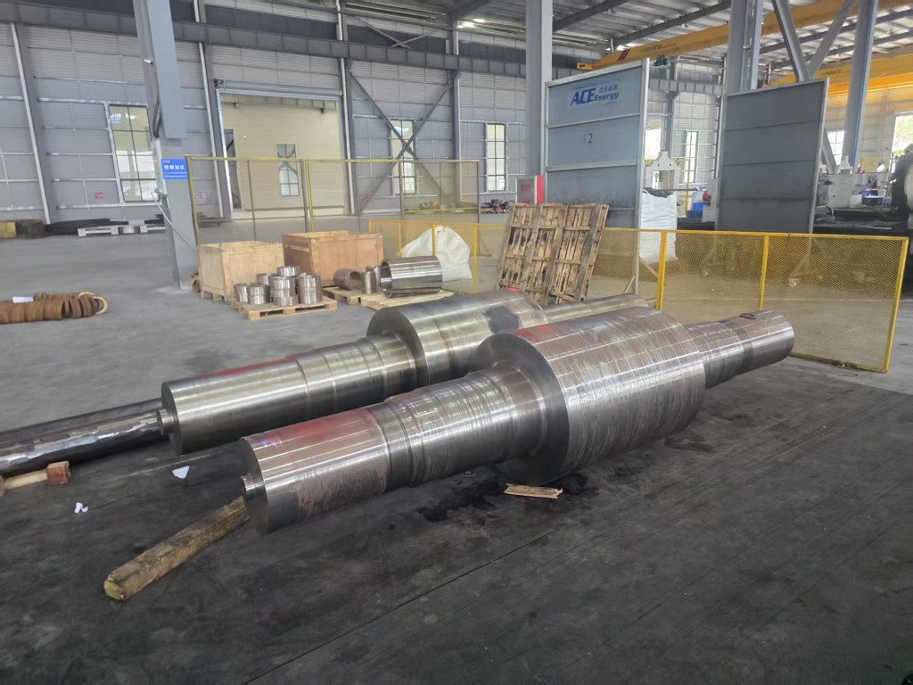
Mining and metallurgy run on impact. Cone crusher main shafts, hydraulic breaker cylinder blocks, mill bearing housings, roller shafts and straightening rolls are typical open die parts, usually in alloy steel with a hardened or surface treated working zone. Petrochemical buyers specify a similar route for valve bodies, blowout preventers, mandrel hangers and tube sheets, where pressure retention and hydrogen service often dictate the inspection level. A supplier that covers forging, heat treatment, machining, welding and surface finishing removes a great deal of coordination risk, and our full range of forged components is organised by industry so a part can be matched to an application quickly.
 Cone Crusher Main Shaft ForgingsManufactured from a variety of materials and treated with special heat processes, they feature ultra-high strength and a "hard exterior, tough interior" structure, mak...View Product →
How to specify open die forgings in an RFQ
An enquiry that gets a fast, comparable answer contains the following items.
- A finished part drawing plus a separate forging drawing showing machining allowance and parting lines.
- Material grade, material standard and any acceptable alternatives.
- Minimum reduction ratio and the required grain flow direction.
- Heat treatment condition with mechanical test requirements, sampling position and test standard.
- Non-destructive examination requirements, typically ultrasonic testing with an acceptance level.
- Delivery condition: as forged, rough machined, or finished and painted.
- Quantity, target delivery date, and whether first article approval is required.
Open die forging remains the practical route for large, low volume, high integrity metal parts, and the buying decision usually comes down to weight, batch size and how much machining is planned. Get the reduction ratio, heat treatment condition and inspection level right in the specification, and the process delivers a part with continuous grain flow and predictable properties. Leave them vague, and the extra cost reappears later as rework, rejected test bars or a slipped delivery date. Use the comparisons in this guide as the starting point for that conversation with your forging supplier.
Message Us Right Now!
-
Mobile Terminal
-
Quick Links
Products About Us Equipment & Capacity Quality News Contact Us -
Product Category
Power‑Generation Forgings OEM Machined Forgings CUSTOMIZED MADE FORGING PARTS Ship and Port Machinery Forgings Mining and Metallurgy Forgings Food and Feed Machinery Forgings Welding Fabrication Petrochemical Industry Forgings -
Contact Us
Mob.: +86-173 7218 0878 Tel.: +86-515-8389 0396 E-mail: ivy.zhai@aceprocess.cn Add.: No.21 Jinfeng Road, Economic Development Park, Dafeng District, Yancheng City, Jiangsu, China
Copyright © 2025 Yancheng ACE Machinery Co., Ltd. All Rights Reserved.
China open die forgings manufacturer
custom precision forgings supplier
