

 English
 中文简体
中文简体

Industry News


Industry News
How are Wind Turbine Gearbox Forgings manufactured?
2026-06-19
Wind Turbine Gearbox Forgings are manufactured through a precisely controlled multi-stage process: high-quality alloy steel billets are heated to forging temperature, shaped under high-tonnage press or hammer equipment, then subjected to heat treatment, precision machining, and comprehensive quality inspection before delivery. The entire sequence is engineered to produce components with superior grain structure, fatigue resistance, and dimensional accuracy — properties that cast or machined-from-bar alternatives cannot match for the extreme cyclic loading conditions inside a wind turbine gearbox.
The manufacturing process is not a single operation but an integrated chain. Each stage directly influences the mechanical properties and service life of the finished forging. Understanding each step helps engineers, procurement teams, and wind energy developers specify and evaluate forgings with confidence.
Content
- 1 Why the Manufacturing Method Determines Gearbox Forging Performance
- 2 Stage 1: Raw Material Selection and Billet Preparation
- 3 Stage 2: Heating and Temperature Control
- 4 Stage 3: Forging — Open-Die, Ring Rolling, and Closed-Die Operations
- 5 Stage 4: Controlled Cooling After Forging
- 6 Stage 5: Heat Treatment — Developing the Target Mechanical Properties
- 7 Stage 6: Rough Machining and Pre-Inspection
- 8 Stage 7: Precision Machining to Final Dimensional Tolerances
- 9 Stage 8: Final Quality Inspection and Certification
- 10 ACE Group's Manufacturing Capability for Wind Turbine Gearbox Forgings
Why the Manufacturing Method Determines Gearbox Forging Performance
Wind turbine gearboxes operate under some of the most demanding load conditions in industrial machinery. A single 5 MW offshore turbine gearbox transmits peak torques exceeding 4,000 kNm on the low-speed shaft, while internal gear and bearing components experience billions of fatigue load cycles over a 20-year design life. (Source: DNV GL Technical Report, Offshore Wind Turbine Drivetrain Design, 2020.)
The forging process directly addresses these demands by:
- Refining the as-cast grain structure of the billet into a fine, uniform microstructure with aligned grain flow
- Closing internal porosity, shrinkage cavities, and segregation bands present in the original ingot
- Generating beneficial compressive residual stresses in the surface layer that retard fatigue crack initiation
- Producing a homogeneous cross-section with consistent mechanical properties at all depths
Field failure analysis compiled by the European Wind Energy Association (EWEA) consistently identifies gearbox failure as one of the top causes of wind turbine downtime, responsible for approximately 20% of unplanned maintenance events in onshore fleets. The manufacturing quality of internal forgings — ring gears, planet carriers, shafts — is a primary determinant of whether a gearbox meets or falls short of its design life.
Stage 1: Raw Material Selection and Billet Preparation
The manufacturing sequence begins with careful selection of the starting material. Wind turbine gearbox forgings are produced from high-alloy steels specifically formulated for demanding fatigue and impact applications. The most widely specified grades include:
| Steel Grade | Typical Application | Key Properties |
| 18CrNiMo7-6 | Ring gear blanks, planet gear blanks | Case-hardening steel; surface hardness 58-62 HRC after carburizing |
| 42CrMo4 | Shafts, planet carriers, flanges | Quench-and-temper steel; tensile strength 1,000-1,200 MPa |
| 34CrNiMo6 | Large-diameter input shafts | High hardenability; fatigue limit approx. 550 MPa |
| 30CrNiMo8 | Heavy-duty shafts in multi-MW platforms | Yield strength exceeding 900 MPa; excellent toughness |
Steel Cleanliness Requirements
Steel quality for gearbox forgings goes beyond grade selection. Melt cleanliness is critical — non-metallic inclusions such as alumina stringers and sulfide clusters act as fatigue crack initiation sites. Premium gearbox forgings require:
- Vacuum degassing (VD) or vacuum arc remelting (VAR) to reduce dissolved hydrogen below 2 ppm
- Sulfur content below 0.010% by weight
- Non-metallic inclusion ratings compliant with ISO 4967 or ASTM E45 Class C or better
- Chemical composition certification with full heat analysis traceability
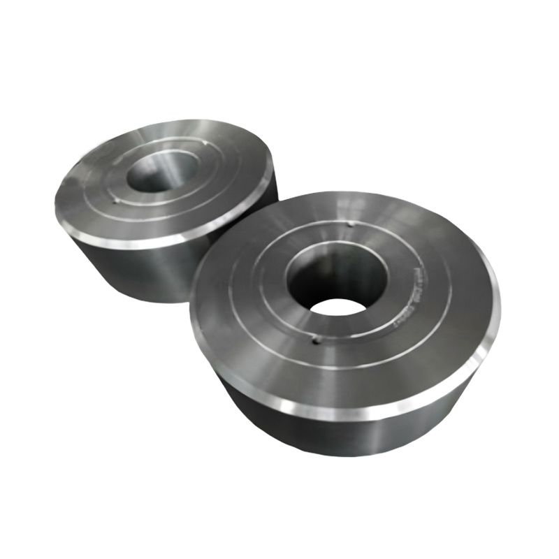
Starting stock is either a continuously cast billet (for smaller cross-sections) or a vacuum-degassed ingot (for large components such as planet carriers exceeding 500 kg). The ingot top (pipe zone) and bottom (segregation zone) are cropped and discarded before the forging sequence begins, ensuring only clean, homogeneous material enters the process.
Stage 2: Heating and Temperature Control
The billet or ingot is loaded into a heating furnace and brought to the forging temperature range. For low-alloy steels used in gearbox forgings, this range is typically 1,100 degrees C to 1,250 degrees C. Temperature uniformity across the cross-section is critical — non-uniform heating produces non-uniform deformation and localized microstructural variation that degrades fatigue performance.
Furnace Types Used in Production
- Energy-efficient natural gas heating furnaces are the standard for large-tonnage billets, providing controlled atmosphere heating with programmable temperature ramps and soak times scaled to billet cross-section
- Induction heating systems are used for smaller billets requiring rapid, precise through-heating with minimal surface oxidation
Soaking time is calculated based on a minimum of 1 minute per millimeter of cross-section diameter to ensure temperature uniformity before forging commences. Inadequate soaking time is a documented source of forging laps and cold shuts that compromise fatigue life. (Source: ASM International, Forging Handbook, 5th Edition.)
Temperature is monitored continuously using calibrated contact pyrometers and non-contact infrared instruments. Forging must be completed before the metal cools below the minimum finish forging temperature — typically 950 degrees C for most alloy steels — to avoid strain hardening and surface cracking from deforming partially recrystallized material.
Stage 3: Forging — Open-Die, Ring Rolling, and Closed-Die Operations
The heated billet is transferred rapidly to the forging press or ring rolling mill. For wind turbine gearbox components, three primary forging methods are employed depending on the component geometry:
Open-Die Forging (Free Forging)
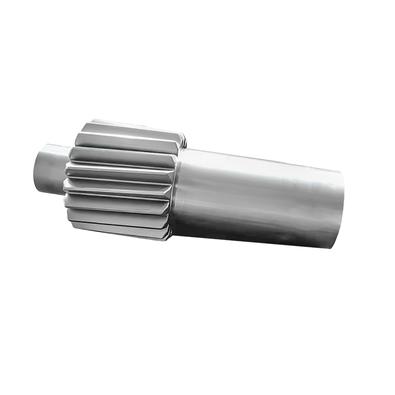
Open-die forging under large hydraulic or electro-hydraulic hammer presses is used for heavy shafts, discs, and pre-forms for subsequent ring rolling. Press capacities used for large wind gearbox components range from 20 MN to 125 MN. The process involves multiple reduction passes, with the billet being rotated and repositioned between each blow. Key process parameter: the forging ratio (initial cross-section area divided by final cross-section area) must typically reach a minimum of 4:1 to 6:1 to ensure adequate grain refinement and void closure.
Ring Rolling
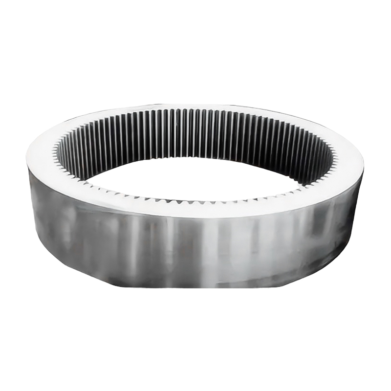
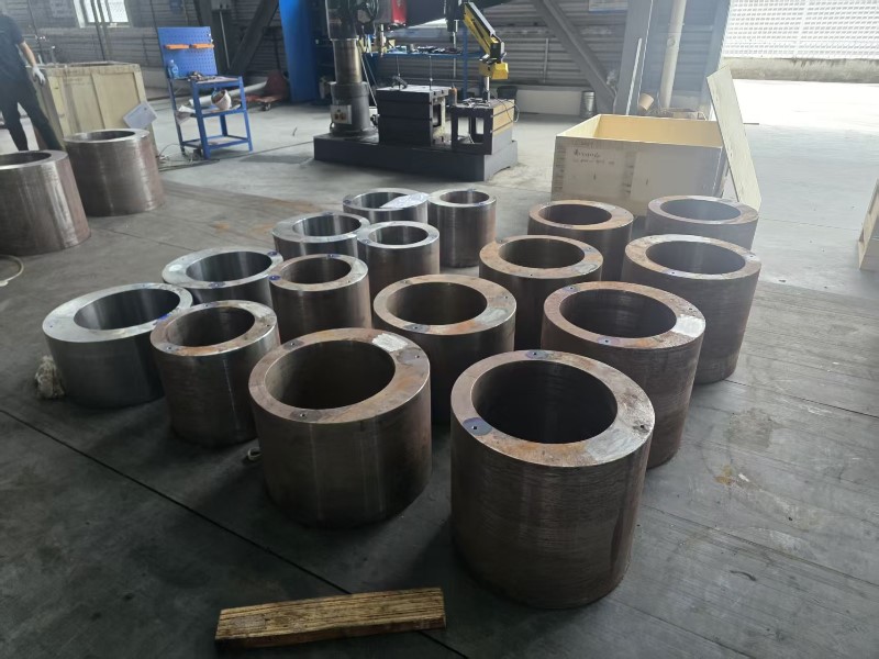
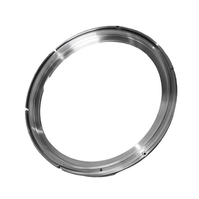
Ring rolling is the primary process for manufacturing ring gear blanks, bearing rings, and flange rings used in wind turbine gearboxes. The process begins with a pre-formed donut-shaped billet (produced by open-die forging and punching), which is then rolled between a driven main roll and an idle mandrel roll to progressively increase the ring diameter while reducing wall thickness.
Vertical ring rolling mills — such as the 1-meter and 1.5-meter capacity machines used in modern heavy forging facilities — can produce rings with outer diameters from several hundred millimeters to over 3,000 mm, wall thicknesses from 50 mm to 400 mm, and heights up to 600 mm. Dimensional control during ring rolling targets a circularity tolerance of less than 0.3% of outer diameter before machining allowance.
Closed-Die Forging
For smaller, geometrically complex components such as planet gear blanks produced in higher volumes, closed-die (impression die) forging is used. The heated billet is struck between matched upper and lower dies that contain the negative profile of the part. This method achieves tighter dimensional tolerances and near-net-shape output, reducing subsequent machining stock and improving material yield compared to open-die forging of the same geometry.
Forging Ratio and Its Effect on Properties
The forging ratio is a critical process parameter that directly determines the degree of grain refinement achieved. The relationship is well-established in metallurgical literature:
- Forging ratio below 2:1 — minimal grain refinement; as-cast dendritic structure partially retained
- Forging ratio 4:1 to 6:1 — significant grain refinement; fatigue properties approach optimal for the alloy grade
- Forging ratio above 8:1 — diminishing returns on grain refinement; risk of anisotropy increasing in transverse direction
Wind gearbox forging specifications typically mandate minimum forging ratios in the 4:1 to 6:1 range, verified by documentation of starting billet dimensions and finished forging dimensions. (Source: AGMA 923-B05, Metallurgical Specifications for Steel Gearing.)
Stage 4: Controlled Cooling After Forging
Once forging is complete, the component must be cooled under controlled conditions. Uncontrolled rapid cooling of large alloy steel forgings introduces:
- Quench cracking from thermal gradient-induced tensile stresses at the surface
- Hydrogen-induced delayed cracking (flaking) in high-alloy steels with residual dissolved hydrogen
- Hard martensitic surface layers that interfere with subsequent machining
Standard practice for large wind gearbox forgings is controlled slow cooling in insulating boxes or programmed furnace cooling at rates of 20 to 50 degrees C per hour until the component reaches below 300 degrees C. This slow cooling allows hydrogen to diffuse out of the steel lattice and prevents thermal shock cracking in thick cross-sections. For very large components (above 1,000 kg), post-forging annealing in a furnace may be specified to fully homogenize the microstructure before heat treatment.
Stage 5: Heat Treatment — Developing the Target Mechanical Properties
Heat treatment is the stage at which the forged microstructure is transformed into the mechanical property profile specified by the design engineer. For wind turbine gearbox forgings, the required heat treatment route depends on the component function and material grade.
Normalizing and Annealing
Applied after forging and before final heat treatment to relieve residual forging stresses, homogenize the microstructure, and improve machinability. Normalizing is performed at 850 to 920 degrees C followed by air cooling. This stage prepares the forging for accurate dimensional machining and ensures consistent response to the subsequent hardening treatment.
Quenching and Tempering
Through-hardened components such as shafts and planet carriers undergo austenitizing at 840 to 880 degrees C, followed by oil or water quenching to form a martensitic structure, then tempering at 550 to 650 degrees C. This sequence produces tensile strengths in the range of 900 to 1,200 MPa combined with Charpy impact values exceeding 60 J at minus 40 degrees C — meeting the low-temperature toughness requirements for offshore turbine applications.
Case Hardening (Carburizing and Quenching)
Gear blanks made from case-hardening steels such as 18CrNiMo7-6 are processed in carburizing furnaces at 880 to 980 degrees C in a carbon-rich atmosphere. The process builds up a carbon-enriched case layer of 0.8 to 2.5 mm effective case depth. After quenching and low-temperature tempering at 150 to 200 degrees C, the case achieves a hardness of 58 to 62 HRC while the core retains toughness with hardness of 30 to 40 HRC. The surface compressive residual stresses generated by the volume expansion of martensite formation significantly enhance bending fatigue strength at the tooth root.
Induction Hardening
Bearing journals, shaft seats, and localized surface zones requiring high hardness are selectively induction-hardened to 54 to 62 HRC surface hardness while the surrounding material remains in its tempered condition. Induction hardening is preferred for large shafts where carburizing the entire component would be impractical and where localized surface hardness is the primary requirement.
Stage 6: Rough Machining and Pre-Inspection
Following heat treatment, the forging undergoes rough machining to remove surface scale, establish datum reference surfaces, and bring external dimensions within rough machining tolerances. Typical rough machining allowances on wind gearbox forgings are 5 to 15 mm per surface depending on forging tolerance and component size.
After rough machining, the component undergoes a critical non-destructive examination (NDE) stage before final machining investment is committed:
- Ultrasonic testing (UT) per EN 10228-3 or ASTM A388 — detects internal discontinuities including pipe remnants, hydrogen flakes, and segregation bands. Acceptance criteria typically require no indications exceeding 2 mm equivalent flat-bottomed hole at any location.
- Magnetic particle inspection (MPI) — detects surface and near-surface cracks on rough-machined surfaces
- Hardness survey — confirms heat treatment response across multiple measurement points on the cross-section
Components that pass rough machining NDE proceed to finish machining. Those with rejectable indications are dispositioned — either repaired where specifications permit or removed from the production stream, protecting the downstream machining investment.
Stage 7: Precision Machining to Final Dimensional Tolerances
Precision machining transforms the heat-treated, rough-machined forging blank into a finished component ready for gear cutting or direct assembly. Key machining operations include:
- CNC turning and boring of bearing journals to roundness tolerances within 5 micrometers and surface roughness Ra 0.4 to 0.8 micrometers
- Gear tooth hobbing or shaping to produce gear tooth profiles to ISO accuracy class 6 or better before case hardening and grinding
- Gear tooth grinding after case hardening to correct thermal distortion and achieve final profile, lead, and pitch tolerances to ISO accuracy class 4 or 5 — the standard for wind turbine gearbox gearing per IEC 61400-4
- Hard turning of bearing seats and housing fits to H7/h6 or tighter interference fit tolerances
- Shot peening of tooth roots to introduce compressive residual stresses extending bending fatigue life by 15 to 25%
Machining operations are performed on CNC machining centers with in-process gauging and coordinate measuring machine (CMM) verification at intermediate stages, ensuring that dimensional deviations are detected and corrected before the next operation rather than discovered at final inspection.
Stage 8: Final Quality Inspection and Certification
Completed wind turbine gearbox forgings undergo a comprehensive final inspection sequence before acceptance for delivery. The inspection scope typically specified by wind turbine OEMs and certification bodies such as DNV, Bureau Veritas, and TUV includes:
| Inspection Type | Method / Standard | Acceptance Basis |
| Dimensional inspection | CMM, gear analysis machine | Drawing tolerances; ISO 1328-1 gear accuracy |
| Ultrasonic testing | EN 10228-3 / ASTM A388 | No indications exceeding specified reference level |
| Magnetic particle inspection | EN 10228-1 / ASTM E1444 | No linear indications; round indications per grade limits |
| Hardness testing | Brinell / Rockwell per EN ISO 6506 | Within specified hardness band at all measurement points |
| Mechanical property testing | Tensile, Charpy impact from prolongation | All values meet or exceed material specification minima |
| Case depth verification | Micro-hardness traverse on test coupon | Effective case depth within specified range at all test points |
| Surface roughness | Contact profilometer | Ra value within drawing specification per zone |
Full material traceability documentation accompanies every accepted forging — from melt heat number and ladle chemical analysis certificate through processing records to final inspection results — enabling complete audit trails required for wind turbine type certification and owner/operator documentation packages.
ACE Group's Manufacturing Capability for Wind Turbine Gearbox Forgings
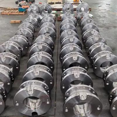
ACE Group's integrated heavy industrial manufacturing system is specifically structured to execute the complete manufacturing chain described above under one organizational roof. Our Wind Turbine Gearbox Forgings are produced through a vertically integrated process spanning:
- Forging: Multi-tonnage electro-hydraulic hammers (3-ton, 5-ton, and 15-ton capacity) and vertical ring rolling mills (1-meter and 1.5-meter) at Jiangsu ACE Energy Technology Co., Ltd. — a 55-acre facility with over 50,018 square meters of production floor area, commencing operations in November 2025
- Heat treatment: On-site natural gas heating furnaces, heat treatment resistance furnaces, quenching tanks, and induction hardening equipment for full metallurgical control without inter-facility transport of semi-finished forgings
- Precision machining: CNC machining centers at Yancheng ACE Machinery Co., Ltd. for dimensional finishing of heat-treated forgings to drawing tolerance
- Surface treatment: Heavy-duty powder coating line at Yancheng ACE Surface Treatment Technology Co., Ltd., achieving one-time coating thickness of 400 micrometers for superior corrosion protection on finished components
This integrated capability eliminates the quality and traceability risks associated with multi-supplier processing chains, and provides customers in the wind energy sector with a single-source manufacturing partner for gearbox forgings from billet through to certified, delivery-ready components.
Message Us Right Now!
-
Mobile Terminal
-
Quick Links
Products About Us Equipment & Capacity Quality News Contact Us -
Product Category
Power‑Generation Forgings OEM Machined Forgings CUSTOMIZED MADE FORGING PARTS Ship and Port Machinery Forgings Mining and Metallurgy Forgings Food and Feed Machinery Forgings Welding Fabrication Petrochemical Industry Forgings -
Contact Us
Mob.: +86-173 7218 0878 Tel.: +86-515-8389 0396 E-mail: ivy.zhai@aceprocess.cn Add.: No.21 Jinfeng Road, Economic Development Park, Dafeng District, Yancheng City, Jiangsu, China
Copyright © 2025 Yancheng ACE Machinery Co., Ltd. All Rights Reserved.
China open die forgings manufacturer
custom precision forgings supplier
