

 English
 中文简体
中文简体

Industry News
Home / News / Industry News / What are the most common causes of failure in wind turbine gearbox forgings?
 Home / News / Industry News / What are the most common causes of failure in wind turbine gearbox forgings?
Industry News
What are the most common causes of failure in wind turbine gearbox forgings?
2026-06-26
The most common causes of failure in Wind Turbine Gearbox Forgings are material fatigue, subsurface inclusion defects, inadequate heat treatment, misalignment-induced stress concentrations, and lubrication breakdown. Studies from the National Renewable Energy Laboratory (NREL) show that gearbox failures account for approximately 20% of wind turbine downtime, making them the single largest source of unplanned maintenance cost in the industry. Understanding the root causes at the forging and materials level is the most effective path to preventing premature failure.
Content
- 1 Material Fatigue: The Leading Mechanical Failure Mode
- 2 Subsurface Inclusions and Internal Defects
- 3 Inadequate Heat Treatment and Case Hardening Failures
- 4 Forging Flow Line Defects and Poor Grain Structure
- 5 Lubrication Failure and Its Connection to Forging Surface Quality
- 6 Misalignment and Assembly-Induced Stress Concentrations
- 7 Corrosion and Environmental Degradation
- 8 How High-Quality Forgings Reduce Failure Risk
- 9 Summary: Failure Causes at a Glance
Material Fatigue: The Leading Mechanical Failure Mode
Fatigue is responsible for the majority of gearbox forging failures in operating wind turbines. Unlike static overload, fatigue damage accumulates invisibly over millions of load cycles before a crack propagates to the surface.
How Fatigue Initiates in Forgings
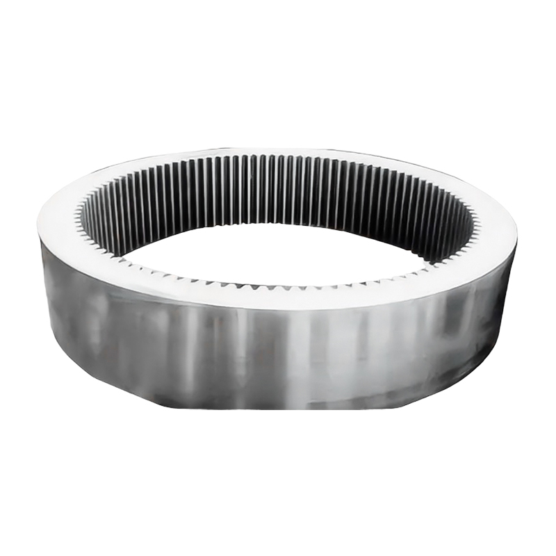
In gearbox ring gears, planet carriers, and output shafts, cyclic bending and torsional loads create micro-cracks at stress-concentration points such as keyways, fillets, and cross-bore intersections. According to a 2019 analysis published in Wind Energy (Wiley), over 60% of gear tooth failures in wind turbine gearboxes originate from fatigue cracks that began at or just below the contact surface.
Variable Load Spectrum Aggravates Fatigue
Wind turbines experience highly irregular load spectra. Gusts, turbulence, and start-stop cycles mean gearbox components rarely see a steady-state load. This variable amplitude loading accelerates fatigue damage accumulation compared to constant-amplitude laboratory test conditions, which is why many standard fatigue ratings underestimate real-world service life.
Subsurface Inclusions and Internal Defects
Even a high-quality forging can harbor internal defects that serve as initiation sites for premature cracking. The most problematic are non-metallic inclusions -- oxides, sulfides, and silicates -- introduced during steelmaking or retained through inadequate processing.
Inclusion Types and Their Effects
| Inclusion Type | Origin | Primary Damage Mechanism |
|---|---|---|
| Oxide stringers | Deoxidation residues | Crack nucleation under rolling contact fatigue |
| Sulfide inclusions (MnS) | High sulfur steel grades | Delamination and spalling in gear tooth root |
| Silicate clusters | Refractory contamination | Subsurface void formation leading to pitting |
| Hydrogen flakes | Absorbed hydrogen in large forgings | Internal cracking during or after forging |
Source: ASM International, Failure Analysis of Heat Treated Steel Components, 2008.
For large gearbox forgings -- planet carriers weighing over 2,000 kg are common in 3 MW+ turbines -- hydrogen-induced flaking is a particularly serious risk if post-forge slow cooling or annealing procedures are not strictly followed.
Inadequate Heat Treatment and Case Hardening Failures
Gearbox forgings must achieve a precise balance between a hard, wear-resistant surface layer and a tough, ductile core. When heat treatment is poorly controlled, this balance is lost, and failures occur rapidly in service.
Common Heat Treatment Errors
- Insufficient case depth in carburized or nitrided gears, causing sub-case fatigue cracking
- Non-uniform hardening due to inadequate quench agitation, leaving soft spots in the forging
- Decarburization of the surface layer during forging or normalizing, reducing surface fatigue strength by up to 30% (Source: AGMA 923-B05, Metallurgical Specification for Steel Gearing)
- Quench cracking from excessive thermal gradients in thick-section components
- Retained austenite above acceptable thresholds, which transforms under service stress and causes dimensional instability
For wind turbine gearbox ring gears -- which may have wall thicknesses exceeding 150 mm -- achieving uniform through-hardening requires carefully selected steel grades with adequate hardenability (typically 18CrNiMo7-6 or 20MnCr5) and precisely controlled quench media and temperature profiles.
Forging Flow Line Defects and Poor Grain Structure
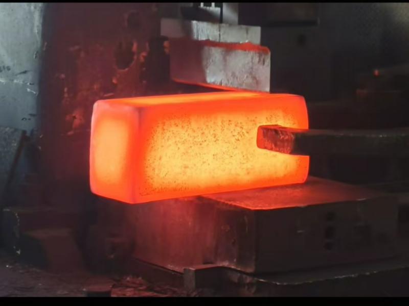
The mechanical properties of a finished gearbox forging are directly determined by the internal grain flow created during the forging process. Poorly designed forging dies or incorrect reduction ratios can create defects that remain hidden until the component fails in service.
Key Structural Defects from Forging Practice
- Laps and cold shuts: Formed when metal folds over itself during die filling, creating a seam that acts as a pre-existing crack
- Flow-through defects: Occur when material flows incorrectly around cores or mandrels, disrupting grain continuity
- Coarse grain bands: Result from insufficient hot-work reduction or reheating above the grain-coarsening temperature, reducing impact toughness by as much as 40% compared to fine-grained microstructures (Source: ASTM E112 grain size standards and industry forging data)
- Segregation centerlines: In large-diameter shaft forgings, alloy segregation from the original ingot may persist even after forging, creating zones of differing hardness and fatigue resistance
High-quality manufacturers address these risks through rigorous process design, including adequate forging reduction ratios (typically a minimum 4:1 reduction from ingot), controlled reheating temperatures, and mandatory ultrasonic testing (UT) of all finished forgings per standards such as EN 10228-3 or ASTM A388.
Lubrication Failure and Its Connection to Forging Surface Quality
Lubrication failure is often treated as a purely operational issue, but the surface finish and dimensional accuracy of gearbox forgings directly determines how well a lubricant film is maintained under load.
How Surface Condition Accelerates Wear
Rough or irregular forging surfaces -- even after machining -- create high asperity contact pressures that puncture the elastohydrodynamic (EHL) lubricant film. Once metal-to-metal contact occurs, surface temperatures at micro-contact points can exceed 300 degrees C locally (Source: Tribology International, Vol. 44, 2011), leading to micro-welding, scuffing, and rapid surface fatigue known as micropitting.
NREL's Gearbox Reliability Collaborative (GRC) identified micropitting on planet and sun gear teeth as a primary damage mode in field-returned gearboxes, with surface roughness values above Ra 0.4 micron significantly increasing micropitting risk even with correct lubricant viscosity.
Lubricant Contamination from Forging Residues
Scale, oxide particles, or residual shot-blast media left in internal cavities of gearbox housings or hollow shafts can circulate in service oil, causing abrasive three-body wear that damages bearing races and gear flanks far faster than design predictions assume.
Misalignment and Assembly-Induced Stress Concentrations
Even a perfectly manufactured gearbox forging can fail prematurely if the gearbox is incorrectly assembled or if drivetrain misalignment transmits unexpected bending moments into the gearbox housing and shafts.
Sources of Misalignment in Wind Turbine Drivetrains
- Main bearing wear allowing rotor shaft deflection that loads gearbox input shaft asymmetrically
- Tower settlement or nacelle bedplate distortion introducing angular misalignment between gearbox and generator
- Incorrect torque arm bushing installation, concentrating reaction forces at specific points on the gearbox housing forging
- Planet carrier bore misalignment exceeding 0.05 mm, which unloads some planet gears while overloading others -- a known contributor to premature planet gear and bearing failures (Source: GL Garrad Hassan Wind Turbine Technology, 2012)
Corrosion and Environmental Degradation
Offshore and coastal wind turbines expose gearbox components to humidity, salt spray, and temperature cycling that accelerates corrosion fatigue -- a combination of mechanical fatigue and corrosive attack that is more damaging than either factor alone.
Research published in the International Journal of Fatigue (2017) demonstrated that corrosion fatigue reduces the fatigue limit of low-alloy steel gearbox shafts by up to 50% compared to tests conducted in dry air. Surface pits from corrosion act as stress concentrators with effective stress intensity factors comparable to machined notches.
For offshore applications, gearbox forging specifications must address corrosion resistance through material selection, protective coatings, and sealed lubrication systems -- not simply rely on onshore-grade component standards.
How High-Quality Forgings Reduce Failure Risk
Selecting forgings produced under rigorous quality management directly addresses the root causes listed above. Key quality indicators to specify include:
- Clean steel production with vacuum degassing (VD) or vacuum arc remelting (VAR) to minimize inclusion content
- Controlled forging reduction ratios and validated die designs to ensure consistent grain flow
- Full traceability of heat treatment records, including time-temperature charts for each batch
- 100% ultrasonic testing (UT) per EN 10228-3 Class 3 or equivalent, plus magnetic particle inspection (MPI) of all finished surfaces
- Mechanical test certificates (tensile, impact, hardness) from specimens cut from test prolongations forged integrally with the component
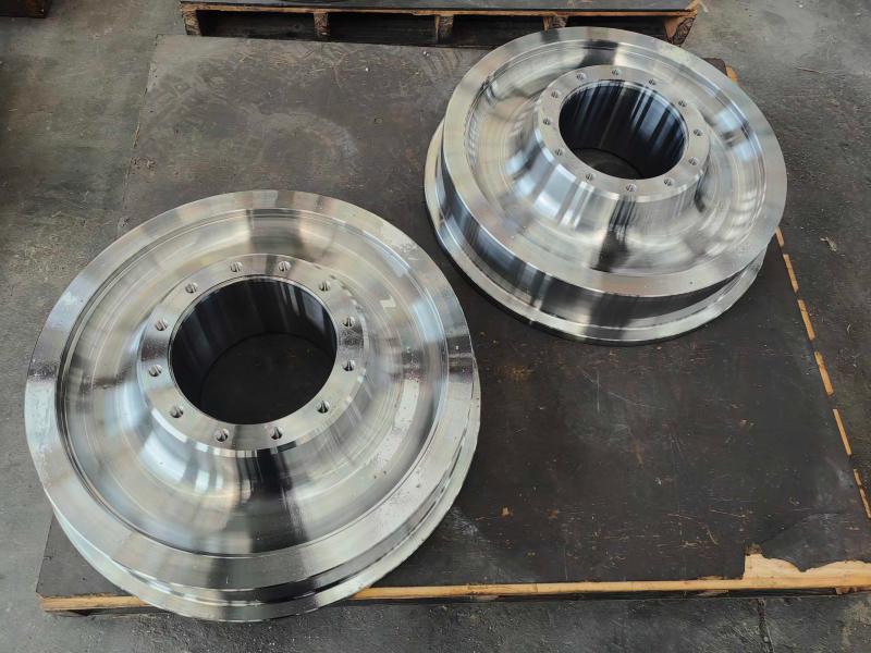
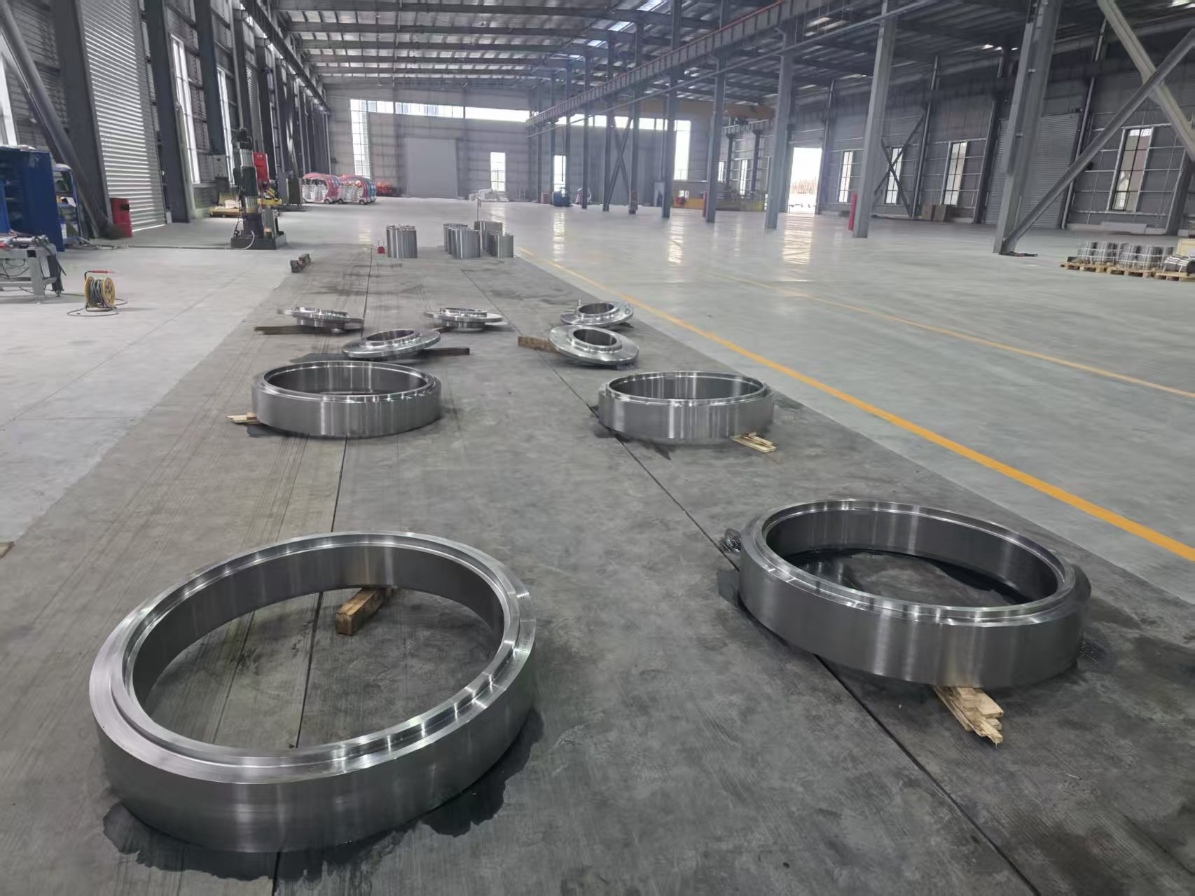
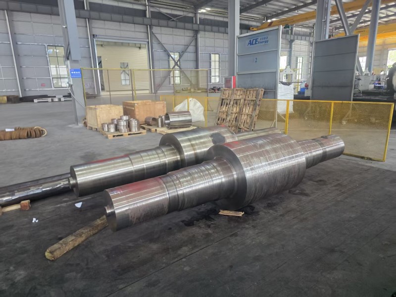
For procurement teams and wind turbine OEMs evaluating forging suppliers, our Wind Turbine Gearbox Forgings are manufactured to meet these exacting standards -- covering ring gears, planet carriers, output shafts, and housing components for turbines from 1.5 MW to 6 MW class, with full material certification and NDE documentation supplied with every order.
Summary: Failure Causes at a Glance
| Failure Cause | Primary Component Affected | Prevention Strategy |
|---|---|---|
| Material fatigue | Gear teeth, shafts | Accurate load spectrum design, shot peening |
| Subsurface inclusions | Planet carriers, ring gears | Vacuum-degassed clean steel, UT inspection |
| Heat treatment errors | All gear and shaft forgings | Certified process records, test prolongations |
| Forging grain defects | Housing, planet carriers | Minimum 4:1 forging reduction, die validation |
| Lubrication failure | Gear flanks, bearing races | Surface finish control, clean assembly |
| Misalignment | Input shaft, planet carrier bores | Alignment verification, main bearing monitoring |
| Corrosion fatigue | Offshore gearbox shafts | Sealed lubrication, corrosion-resistant coatings |
Message Us Right Now!
-
Mobile Terminal
-
Quick Links
Products About Us Equipment & Capacity Quality News Contact Us -
Product Category
Power‑Generation Forgings OEM Machined Forgings CUSTOMIZED MADE FORGING PARTS Ship and Port Machinery Forgings Mining and Metallurgy Forgings Food and Feed Machinery Forgings Welding Fabrication Petrochemical Industry Forgings -
Contact Us
Mob.: +86-173 7218 0878 Tel.: +86-515-8389 0396 E-mail: ivy.zhai@aceprocess.cn Add.: No.21 Jinfeng Road, Economic Development Park, Dafeng District, Yancheng City, Jiangsu, China
Copyright © 2025 Yancheng ACE Machinery Co., Ltd. All Rights Reserved.
China open die forgings manufacturer
custom precision forgings supplier
