
 English
 中文简体
中文简体
Industry News

Industry News
What are the characteristics of Hydro Turbine Forgings?
2026-05-29
Hydro turbine forgings are defined by a specific and demanding set of characteristics that distinguish them from forgings used in any other industrial application. The six most critical characteristics are: superior mechanical strength, excellent fatigue resistance, high cavitation and erosion resistance, precise dimensional integrity across large section sizes, consistent through-thickness properties, and long-term corrosion resistance in continuous water contact. Each of these characteristics is a direct response to the extreme hydraulic, mechanical, and environmental conditions present inside operating hydro turbines — conditions that no other manufacturing process or material selection approach can address as reliably as properly specified and produced forgings.
The sections below examine each characteristic in detail, with supporting data and practical context to explain how these properties translate into real-world turbine performance and longevity.
Content
- 1 High Mechanical Strength Across Large Cross-Sections
- 2 Outstanding Fatigue Resistance Under Cyclic Loading
- 3 Cavitation Erosion Resistance: Protecting Surfaces from Hydraulic Destruction
- 4 Dimensional Integrity and Precision Across Massive Components
- 5 Through-Thickness Property Uniformity
- 6 Corrosion Resistance in Continuous Water Contact
- 7 Internal Cleanliness and Freedom from Defects
- 8 Weldability: Enabling Repair and Fabrication
- 9 Characteristic Properties Compared: Hydro Turbine Forgings vs. Alternative Manufacturing Routes
- 10 Traceability and Documentation: A Characteristic That Defines Quality Assurance
- 11 Characteristics by Component Type: A Practical Reference
- 12 How These Characteristics Translate into Extended Service Life
High Mechanical Strength Across Large Cross-Sections
The most fundamental characteristic of any hydro turbine forging is its ability to carry very high mechanical loads without yielding, cracking, or deforming permanently. Turbine main shafts, runner hubs, and guide vane carriers must simultaneously resist torsion, bending, hydraulic pressure, and centrifugal forces — often in combinations that approach the design limits of the material.
Tensile and Yield Strength Requirements
Alloy steel turbine shaft forgings are typically specified with minimum yield strengths of 550 to 750 MPa and tensile strengths of 700 to 900 MPa, depending on the alloy grade and service conditions. Martensitic stainless steel runner forgings (CA6NM grade) are specified at minimum 550 MPa yield strength and 755 MPa tensile strength in the fully heat-treated condition. These strength levels must be achieved and verified not just at the surface of the forging but uniformly throughout the entire cross-section — including the center of a turbine shaft that may be 1,000 to 2,000 mm in diameter.
Achieving uniform through-section properties in such large cross-sections is one of the most technically challenging aspects of turbine forging production. The quenching rate at the center of a 1,500 mm diameter shaft is dramatically slower than at the surface, resulting in a coarser microstructure and potentially lower strength if the alloy is not correctly selected for the section size. This is why turbine shaft forgings are almost always produced from chromium-molybdenum or chromium-molybdenum-vanadium alloy steels with sufficient hardenability to achieve the required microstructure even at slow cooling rates deep within the section.
Toughness and Impact Resistance
High static strength alone is insufficient — a turbine forging must also absorb energy without fracturing when subjected to sudden loads from water hammer events, load rejection transients, or grid fault conditions. This requires high fracture toughness, measured by Charpy V-notch impact energy. Typical specifications for turbine shaft forgings require Charpy impact energy of 40 to 70 J at 0°C, tested on specimens oriented in the most unfavorable direction relative to the forging grain flow. For Pelton runner bucket forgings exposed to high-velocity water jet impacts, even higher toughness values are specified to resist crack propagation from surface impact damage.
Outstanding Fatigue Resistance Under Cyclic Loading
Fatigue — the progressive development and propagation of cracks under cyclic stress — is the primary failure mode for rotating turbine components. A hydro turbine that starts and stops once per day accumulates approximately 15,000 load cycles over a 40-year service life, with each cycle subjecting shafts, runner hubs, and guide vane stems to significant stress reversals. Superimposed on these low-cycle fatigue loads are high-frequency vibrations from hydraulic vortex shedding, rotor-stator interaction, and draft tube surging that can reach frequencies of 5 to 50 Hz — accumulating millions of high-cycle fatigue events per year of operation.
The Role of Grain Structure in Fatigue Life
The forging process directly enhances fatigue life by refining and aligning the steel's grain structure. Controlled deformation during hot forging breaks up coarse dendritic solidification structures from the original ingot, replacing them with a fine, equiaxed grain structure. Forged components consistently demonstrate fatigue endurance limits 30 to 60% higher than cast equivalents of the same composition, because the refined grain structure provides more grain boundaries to deflect and arrest growing fatigue cracks, and because forging eliminates the internal porosity and inclusion clusters that act as fatigue crack initiation sites in castings.
Surface Finish and Stress Concentration Control
Even in a metallurgically excellent forging, fatigue cracks almost always initiate at surface stress concentrations — keyways, fillet radii, seal grooves, and surface roughness peaks. Turbine forging specifications therefore include stringent requirements for surface finish (typically Ra ≤ 1.6 µm at critical sections) and minimum fillet radii (often 30 to 80 mm at shaft shoulder transitions, compared to 5 to 10 mm in less critical applications). These geometric requirements are only achievable because the superior machinability of high-quality forgings allows precision machining to tight tolerances without introducing machining-induced surface damage.
Cavitation Erosion Resistance: Protecting Surfaces from Hydraulic Destruction
Cavitation erosion is arguably the most distinctive and challenging degradation mechanism specific to hydro turbine components. It occurs when low local water pressures cause water to vaporize and form bubbles, which then collapse violently when they move into higher-pressure zones — generating localized pressure pulses exceeding 1 GPa that physically erode metal surfaces at rates that can remove millimeters of material per year in severe cases.
Why Martensitic Stainless Steel Is the Standard for Hydraulic Components
The resistance of a material to cavitation erosion correlates strongly with its hardness, yield strength, and work-hardening capacity — properties that are all enhanced by the forging process and by the selection of martensitic stainless steel grades. The most widely used grade, CA6NM (13% Cr, 4% Ni, 0.5% Mo), offers a combination of cavitation erosion resistance approximately 3 to 5 times greater than carbon steel in standardized vibratory cavitation tests, while also providing the corrosion resistance needed for continuous operation in fresh and mildly saline water.
Forged CA6NM components benefit from a uniform, fine-grained martensitic microstructure throughout their cross-section. Cast components of the same alloy may exhibit coarser grain sizes, dendritic segregation, and local composition variations that reduce cavitation resistance in specific zones — precisely the zones where cavitation attack tends to be most intense, such as the suction face of runner blades near their trailing edges.
Abrasive Wear Resistance in Sediment-Laden Water
Many hydro turbines, particularly those in Asia, South America, and mountainous regions, operate on rivers carrying significant sediment loads — quartz and feldspar particles with hardness values of 7 to 8 on the Mohs scale. These particles abrade turbine runner blades, guide vane surfaces, and seal faces at rates proportional to particle concentration, particle size, flow velocity, and the hardness of the turbine material. Forged stainless steel components with surface hardness of 250 to 350 HB resist abrasive wear significantly better than softer carbon steel alternatives, with wear rates in field tests typically 40 to 60% lower at equivalent sediment concentrations and flow velocities.
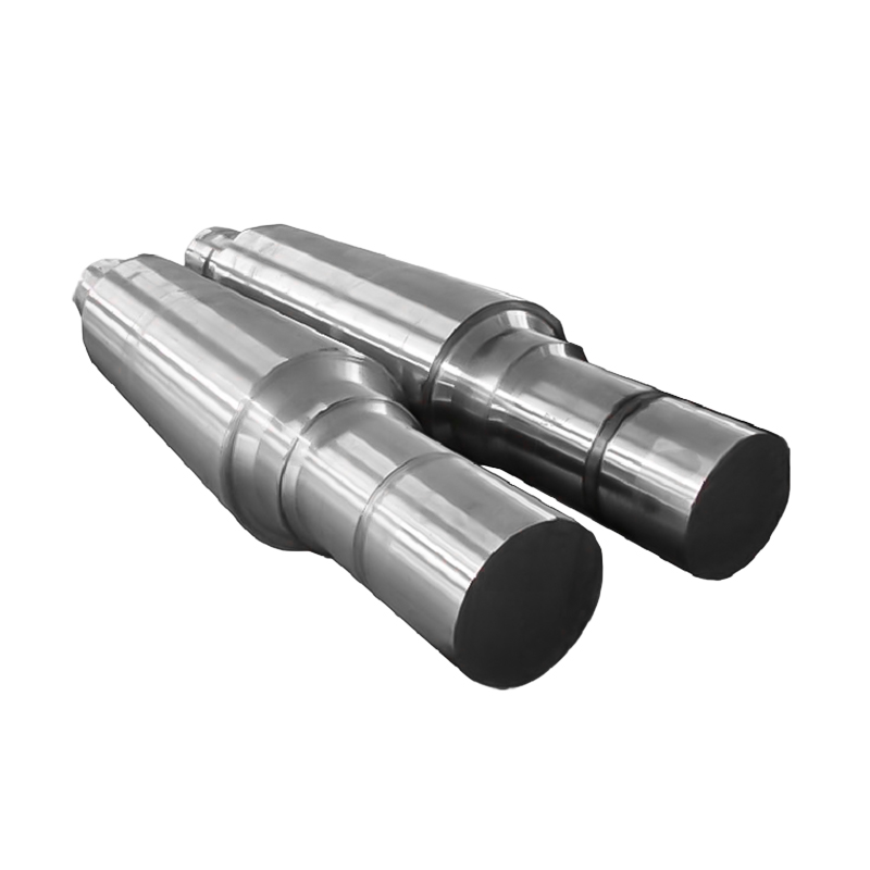
Dimensional Integrity and Precision Across Massive Components
Hydro turbine forgings are among the largest precision mechanical components produced in any industry. A main shaft forging for a large Francis turbine may be 4 to 8 meters in length, 1,000 to 2,000 mm in diameter, and weigh 50 to 150 tonnes. A Kaplan turbine hub forging for a very large river installation can exceed 200 tonnes. At these scales, maintaining the dimensional accuracy and geometric tolerances required for correct installation and operation is a significant engineering and manufacturing challenge.
Straightness and Roundness Requirements
Turbine main shafts must be straight to within 0.1 to 0.2 mm per meter of length after final machining, to avoid vibration caused by shaft bow. Roundness of journal surfaces — where the shaft runs in guide bearings — is typically specified to within 0.02 to 0.05 mm total indicator runout. Achieving these tolerances in a component weighing 50 tonnes requires that the forging itself be free of residual stress-induced distortion, that heat treatment be carried out in a controlled manner that does not introduce asymmetric thermal stresses, and that the forging stock allowance is sufficient to machine away any surface decarburization or scale without leaving subsurface defects exposed.
Residual Stress Management
Large forgings accumulate significant residual stresses during both the forging operation and subsequent heat treatment — particularly during quenching, where rapid surface cooling creates a compressive surface layer over a tensile core. If these residual stresses are not relieved before machining, material removal during rough machining can cause the forging to distort, destroying dimensional accuracy that cannot be recovered without re-machining. A final stress-relief heat treatment at 550°C to 650°C for several hours per 25 mm of section thickness is therefore a standard characteristic of well-produced turbine forgings, and its completion must be verified in the material certification documentation.
Through-Thickness Property Uniformity
One of the most technically demanding characteristics of hydro turbine forgings is the requirement that mechanical properties be essentially uniform from the surface to the center of the component — a condition known as through-thickness property uniformity or hardenability adequacy.
This characteristic is verified by cutting test specimens from multiple locations within the forging, including from the center of the largest cross-section. Specifications typically require that center-of-section tensile properties do not fall more than 10 to 15% below the surface values, and that Charpy impact energy at the center meets the same absolute minimum as the surface specimens. For a shaft with a 1,500 mm diameter, the center is approximately 750 mm from any surface — a depth at which the cooling rate during quenching may be less than one-tenth of the surface cooling rate, making hardenability a stringent alloy design requirement.
This is why alloys like 34CrNiMo6 and 30CrNiMo8 — with nickel contents of 1.4% and 1.8–2.2% respectively — are specified for the largest turbine shaft forgings. The nickel addition shifts the continuous cooling transformation (CCT) diagram to longer times, allowing the deep sections of large forgings to develop sufficient martensite or bainite during quenching to meet strength requirements.
Corrosion Resistance in Continuous Water Contact
Hydro turbine components operate in continuous contact with flowing water — sometimes for years between maintenance shutdowns. This places specific requirements on the corrosion resistance of forging materials, which vary significantly depending on the water chemistry of the specific installation.
Freshwater and Mildly Corrosive Environments
For the majority of inland hydro stations operating on rivers or reservoirs with near-neutral pH fresh water, martensitic stainless steel forgings (CA6NM / 13Cr4Ni) provide adequate corrosion resistance for the hydraulically loaded components such as runners and guide vanes. Carbon steel forgings used for structural components (shafts, flanges, covers) in these environments are protected by paint coatings and cathodic protection systems rather than by inherent alloy corrosion resistance. The passive chromium oxide film on CA6NM stainless steel maintains its integrity in water with pH 6 to 9 — covering the range encountered in virtually all natural freshwater hydro installations.
Aggressive Water Chemistry Applications
In pumped storage schemes operating in regions with acidic groundwater, in tidal or run-of-river installations with brackish water, or in industrial hydro applications where process water contains dissolved chemicals, standard CA6NM stainless steel may be insufficient. These applications require forgings from higher-alloyed grades such as duplex stainless steel (2205 / S31803, with 22% Cr and 5% Ni) or super-duplex grades (25% Cr), which offer pitting corrosion resistance indices (PREN = Cr + 3.3Mo + 16N) of 35 to 43, compared to approximately 25 for CA6NM. The forgeability of duplex grades is acceptable but requires careful control of forging temperature and reduction ratio to avoid embrittlement from sigma phase formation.
Crevice Corrosion and Galvanic Compatibility
A characteristic often overlooked in turbine forging specification is the risk of crevice corrosion at interfaces between dissimilar metals or at tight joints between mating forged components. Blade-to-hub interfaces on Kaplan runners, guide vane stem-to-bushing interfaces, and bolt hole surfaces are all potential crevice corrosion sites. Design standards typically require that mating materials have a galvanic potential difference of less than 50 mV in the service water chemistry, and that surface treatments or sealants are applied at interfaces to prevent water ingress into crevice geometries.
Internal Cleanliness and Freedom from Defects
A defining characteristic of premium hydro turbine forgings is the extraordinary level of internal cleanliness required — not merely freedom from gross defects detectable by ultrasonic testing, but control of microscopic non-metallic inclusion populations that determine fatigue performance in high-cycle regimes.
Steel Cleanliness and Non-Metallic Inclusions
Non-metallic inclusions — oxides, sulfides, and silicates entrapped in the steel during melting and solidification — act as stress concentrators that initiate fatigue cracks under cyclic loading. The ASTM E45 inclusion rating system grades inclusions on a scale of 0 (cleanest) to 3 (most severe) for both thin and heavy series. Premium turbine shaft forgings typically require inclusion ratings of maximum 1.5 thin and 1.0 heavy for all inclusion types — ratings that can only be achieved through vacuum degassing or ladle refining followed by calcium treatment to modify inclusion morphology from elongated stringers to rounded, less damaging spheroids.
Hydrogen content is separately controlled, with requirements typically below 1.5 ppm after vacuum degassing, to prevent hydrogen-induced cracking (also called flaking or white spots) that can occur in large, slowly cooled forgings if dissolved hydrogen precipitates as molecular hydrogen gas at grain boundaries and inclusion interfaces.
Ultrasonic Acceptance Standards
The internal quality of finished turbine forgings is verified by full volumetric ultrasonic testing (UT) to standards referenced in international codes such as EN 10228-3 (for alloy steel shaft forgings) or ASTM A388. These standards define acceptance levels in terms of maximum allowable equivalent flaw size — typically expressed as a flat-bottom hole (FBH) diameter. Critical turbine shaft forgings are typically accepted to quality class 3 or better of EN 10228-3, corresponding to no indication exceeding 3 mm FBH equivalent diameter, with additional restrictions on clustered indications within any defined reference area. For the most demanding applications, 2 mm FBH limits are specified — a requirement that virtually mandates electroslag remelted (ESR) or vacuum arc remelted (VAR) ingot stock.
Weldability: Enabling Repair and Fabrication
An important but often underappreciated characteristic of hydro turbine forgings is weldability — the ability of the forging material to be welded without cracking, embrittlement, or unacceptable loss of mechanical properties in the heat-affected zone (HAZ).
Weldability matters for two primary reasons. First, many turbine runner components are manufactured as a combination of forged and welded elements — for example, a Francis turbine runner where the crown and band are forged separately and then welded to the cast or forged blades. Second, cavitation erosion damage to runner blades is repaired by depositing weld metal in the eroded areas and grinding back to the original profile — a maintenance procedure that may be repeated multiple times over a turbine's service life.
CA6NM stainless steel is specifically valued in the turbine industry for its good weldability relative to other martensitic stainless grades. With a carbon equivalent of typically less than 0.06% carbon, it can be welded with matching or over-alloyed filler metals without requiring post-weld heat treatment (PWHT) in many applications — though PWHT at 580°C to 620°C is recommended for highly restrained joints and thick sections to ensure maximum toughness in the HAZ.
Characteristic Properties Compared: Hydro Turbine Forgings vs. Alternative Manufacturing Routes
The following table provides a direct comparison of the key characteristics between forged, cast, and fabricated (welded plate) approaches for equivalent hydro turbine components:
| Characteristic | Forging | Casting | Welded Fabrication |
|---|---|---|---|
| Yield strength (typical) | 550 – 750 MPa | 380 – 550 MPa | 350 – 500 MPa |
| Fatigue endurance limit | Highest | 30–50% lower | Limited by weld quality |
| Internal defect risk | Very low (voids closed by forging) | Higher (shrinkage porosity) | Weld defect risk at joints |
| Grain structure | Fine, aligned, controlled | Coarse, random, dendritic | Plate grain + weld structure |
| Cavitation resistance | Highest for stainless grades | Moderate (composition variation) | Good (plate) / variable (weld) |
| Property uniformity (cross-section) | Excellent | Poor to moderate | Good in plate, reduced at welds |
| Dimensional precision | High (machinable to tight tolerances) | Moderate (distortion on cooling) | Moderate (weld distortion) |
| Service life (typical) | 30 – 50 years | 20 – 35 years | 15 – 30 years |
Traceability and Documentation: A Characteristic That Defines Quality Assurance
A characteristic that distinguishes premium hydro turbine forgings from lower-grade alternatives is the comprehensive documentation trail that accompanies every component from raw material to installed condition. This traceability is not merely a bureaucratic requirement — it is a technically essential characteristic that enables condition monitoring, remaining life assessment, and evidence-based maintenance decisions throughout the turbine's service life.
The documentation package for a premium turbine shaft forging typically includes:
- Heat certificate: Full chemical analysis of the steel heat, including all specified alloying elements and residual elements, with actual values compared to specification limits.
- Ingot and forging process records: Ingot weight, teeming temperature, ingot reduction ratio, forging temperatures at start and end of each forging heat, and total reduction ratio achieved.
- Heat treatment records: Time-temperature charts for all heat treatment stages (normalizing, quenching, tempering, stress relief), including furnace calibration records and thermocouple positions.
- Mechanical test certificates: Tensile, yield, elongation, reduction of area, Charpy impact energy, and hardness results from specimens taken at specified locations within the forging, with specimen orientation and sampling location diagrams.
- Non-destructive examination reports: Ultrasonic testing scan records showing coverage maps and any indication locations; magnetic particle inspection reports covering all critical surfaces; dimensional inspection reports with actual measurements at all specified check points.
- Third-party inspection release certificates: Confirmation by an independent inspection authority that all tests were witnessed and all results meet specification requirements.
This documentation becomes increasingly valuable as the turbine ages. When a crack or anomaly is detected during a scheduled inspection 20 or 30 years after installation, the original material certificates allow engineers to run fracture mechanics calculations based on the actual material properties of the specific forging — rather than assumed minimum specification values — potentially extending the safe operating period by years and deferring expensive component replacement until a planned outage window.
Characteristics by Component Type: A Practical Reference
The specific characteristics that are most important vary by component type and turbine design. The table below summarizes the priority characteristics for the most commonly forged turbine components:
| Component | Most Critical Characteristic | Second Priority | Key Specification Parameter |
|---|---|---|---|
| Main shaft | Fatigue resistance | Through-thickness uniformity | Charpy impact ≥ 55 J at 0°C (center) |
| Francis runner crown / band | Cavitation erosion resistance | Weldability for blade attachment | CA6NM, C ≤ 0.06%, PWHT optional |
| Pelton runner buckets | Impact toughness + erosion resistance | Surface hardness uniformity | 16Cr5Ni, hardness 285–340 HB |
| Kaplan blade pivot shaft | Combined fatigue + corrosion resistance | Dimensional precision | 42CrMo4 or duplex SS, Ra ≤ 0.8 µm |
| Guide vane stem / trunnion | Wear and corrosion resistance | Torsional strength | Duplex SS 2205, yield ≥ 450 MPa |
| Head cover / bottom ring flanges | Internal cleanliness (UT quality) | Dimensional stability after machining | EN 10228-3 Class 3, stress relieved |
| Nozzle bodies / needle valves | Erosion resistance at high velocity | Pressure-retaining integrity | Martensitic SS, hardness ≥ 300 HB |
How These Characteristics Translate into Extended Service Life
The collection of characteristics described above — high strength, fatigue resistance, cavitation resistance, dimensional integrity, internal cleanliness, weldability, and full documentation — does not merely produce a better component in isolation. These characteristics interact and compound to produce turbine installations that operate reliably for 30 to 50 years, with maintenance costs and downtime far below what would be achievable with lower-grade components.
For example: a main shaft with superior fatigue resistance requires less frequent inspection, reducing outage frequency. A runner with high cavitation resistance requires less frequent weld repair, reducing repair costs and the associated downtime. Full material documentation allows condition-based maintenance scheduling, avoiding both premature replacement (wasteful) and operating beyond safe limits (dangerous). Each characteristic contributes individually, and together they produce a propulsion and generating system whose total lifetime cost — accounting for all capital, maintenance, repair, and downtime costs — is substantially lower than an equivalent installation built from lower-specification components, even though the upfront cost of high-quality forgings may be 30 to 80% higher than budget alternatives.


Message Us Right Now!
-
Mobile Terminal
-
Quick Links
Products About Us Equipment & Capacity Quality News Contact Us -
Product Category
Electric Power Energy Forgings Ship and Port Machinery Forgings Mining and Metallurgy Forgings Food and Feed Machinery Forgings Petrochemical Industry Forgings Welding Fabrication CUSTOMIZED FINISH PARTS -
Contact Us
Mob.: +86-173 7218 0878 Tel.: +86-515-8389 0396 E-mail: ivy.zhai@aceprocess.cn Add.: No.21 Jinfeng Road, Economic Development Park, Dafeng District, Yancheng City, Jiangsu, China
Copyright © 2025 Yancheng ACE Machinery Co., Ltd. All Rights Reserved.
China open die forgings manufacturer
custom precision forgings supplier
