
 English
 中文简体
中文简体
Industry News


Industry News
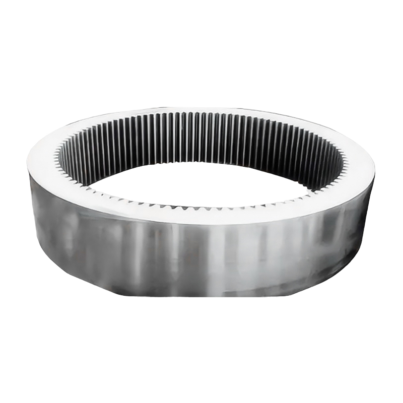
What is the service life of a Wind Turbine Gearbox Forgings?
2026-05-08
The designed service life of wind turbine gearbox forgings is typically 20 years, which aligns with the standard operational lifespan of a modern wind turbine. Under optimal material selection, manufacturing quality, lubrication management, and maintenance practices, high-performance forged components — including ring gears, planet carriers, shafts, and flanges — can meet or exceed this target. However, actual service life varies considerably depending on load cycles, environmental conditions, and maintenance discipline, and in some installations forgings have been documented surviving 25 years or more without replacement.
Content
- 1 Why 20 Years Is the Industry Design Standard
- 2 Key Factors That Determine Service Life of Gearbox Forgings
- 3 Service Life Comparison by Forging Component Type
- 4 How Fatigue Resistance Is Built Into Forgings
- 5 Maintenance Practices That Extend Forging Service Life
- 6 Life Extension Beyond 20 Years
- 7 Signs That Gearbox Forgings Are Approaching End of Service Life
Why 20 Years Is the Industry Design Standard
The 20-year design life for wind turbine drivetrain components is not arbitrary — it is derived from the financial and structural framework of wind energy projects. Most wind farm financing agreements, power purchase contracts, and permitting approvals are structured around a 20-year project term, so turbine designers engineer all major structural and mechanical components to remain within safe fatigue limits over that period.
For gearbox forgings specifically, the IEC 61400-1 standard governs wind turbine design loads, while gear and bearing components are sized according to ISO 6336 (gear fatigue) and ISO 281 (bearing life). These standards define load spectra, safety factors, and fatigue calculations that collectively target a minimum 20-year design life at a reliability level of 97.5% for critical drivetrain forgings.
With growing interest in life extension projects — where operators seek to run turbines beyond their original design life to maximize return on investment — many forged components are now being engineered to 25- or 30-year fatigue lives in newer turbine designs, provided maintenance protocols are followed rigorously.
Key Factors That Determine Service Life of Gearbox Forgings
Service life is not solely a function of design — it is the cumulative result of material quality, manufacturing precision, operational loading, and maintenance quality. The following factors have the greatest measurable influence:
Material Grade and Cleanliness
Wind turbine gearbox forgings are produced from high-alloy steels, most commonly 18CrNiMo7-6, 20MnCr5, or 42CrMo4, selected for their combination of core toughness and surface hardenability. Steel cleanliness — specifically the content of non-metallic inclusions such as sulfides and oxides — is critical: inclusion content above accepted thresholds acts as initiation sites for fatigue cracks. Vacuum degassed, ladle-refined steels with oxygen content below 15 ppm demonstrate significantly longer fatigue lives in rotating bending tests compared to conventionally melted steels.
Forging Process and Grain Structure
The forging process refines the as-cast grain structure of steel ingots into a dense, directional grain flow that follows the geometry of the finished component. This grain flow alignment increases resistance to fatigue crack propagation by 20–40% compared to machined bar stock of the same material grade, according to comparative fatigue testing data. Closed-die forging with controlled reduction ratios ensures consistent grain refinement throughout the cross-section, including in thick-walled sections such as planet carrier webs.
Heat Treatment Quality
Case-hardening processes — typically carburizing followed by quenching and tempering — create a hard, wear-resistant surface layer (typically 0.8–2.0 mm effective case depth) over a tough core. The compressive residual stresses introduced at the case-core interface are a primary mechanism that retards fatigue crack initiation at the tooth root and flank contact zone. Deviations in carburizing atmosphere, temperature uniformity, or quench rate result in non-uniform case depth or retained austenite levels above 25%, both of which measurably reduce fatigue life.
Actual vs. Design Load Spectrum
Gearbox forgings are sized for a calculated load spectrum based on the turbine's site wind class. When a turbine is installed at a site with higher-than-design mean wind speed or more frequent turbulent gusts, cumulative fatigue damage accumulates faster than the design model predicted. Field studies have shown that gearboxes installed in high-turbulence onshore sites can consume their theoretical fatigue life in 12–15 years rather than 20, even when the forgings themselves are free of manufacturing defects.
Lubrication and Contamination Control
Lubricant film thickness at the gear tooth contact zone is the primary factor preventing surface fatigue (micropitting and macropitting). When the lambda ratio — the ratio of oil film thickness to composite surface roughness — falls below 1.0, metal-to-metal contact occurs and surface fatigue initiates rapidly. Water ingress above 0.1% by volume in gearbox oil dramatically accelerates bearing and gear surface fatigue by promoting hydrogen embrittlement and reducing lubricant film strength. Contamination particle counts above ISO 4406 cleanliness class 16/14/11 have been directly correlated with shortened bearing life in wind gearbox monitoring programs.
Service Life Comparison by Forging Component Type
| Forged Component | Typical Design Life | Common Failure Mode | Life-Limiting Factor |
|---|---|---|---|
| Ring gear (annulus) | 20–25 years | Tooth root bending fatigue | Case depth uniformity, load spectrum |
| Planet carrier | 20 years | Structural fatigue at web junctions | Stress concentration, forging grain flow |
| Low-speed shaft (LSS) | 20–25 years | Torsional fatigue, fretting at keyways | Surface finish, fit tolerances |
| High-speed shaft (HSS) | 20 years | Surface pitting at bearing seats | Lubrication quality, alignment |
| Gear flanges and couplings | 20–30 years | Fatigue cracking at bolt holes | Bolt preload, corrosion protection |
How Fatigue Resistance Is Built Into Forgings
Fatigue resistance — the ability to endure millions of repeated stress cycles without crack initiation — is the single most important property of a gearbox forging. Several manufacturing steps work in combination to maximize it:
- Shot peening of gear tooth flanks and roots introduces compressive residual stresses up to 600–800 MPa at the surface, directly opposing the tensile stresses generated during tooth loading that would otherwise drive crack propagation.
- Controlled forging reduction ratios of at least 4:1 are specified to ensure complete breakdown of the original ingot dendritic structure and uniform grain size throughout the forging cross-section.
- Ultrasonic testing (UT) and magnetic particle inspection (MPI) are applied to 100% of gearbox forgings destined for wind energy applications, detecting internal and surface discontinuities that cannot be identified visually.
- Tempering after quenching reduces brittleness introduced by martensitic transformation while retaining hardness above 58–62 HRC at the case for gear tooth components.
- Tight dimensional tolerances (gear accuracy grade AGMA 11 or ISO 5 equivalent) minimize dynamic load amplification caused by tooth spacing and profile errors, directly reducing fatigue loading relative to the nominal transmitted torque.
Maintenance Practices That Extend Forging Service Life
Even the highest-quality forgings will fail prematurely if maintenance is neglected. The following practices have documented positive impact on gearbox forging longevity:
Oil Sampling and Analysis
Regular oil sampling — typically every 3–6 months — detects early wear debris from gear and bearing surfaces before macroscopic damage occurs. Ferrographic analysis of oil samples can identify gear tooth micropitting as much as 6–12 months before it progresses to visible spalling, allowing a planned maintenance intervention rather than an emergency replacement.
Vibration Monitoring
Continuous vibration monitoring via accelerometers mounted on the gearbox housing captures gear mesh frequency harmonics and bearing defect frequencies that are characteristic of specific failure modes in forgings. Condition monitoring systems with automated alarm thresholds allow operators to detect abnormal vibration signatures weeks to months before catastrophic failure, reducing unplanned downtime and secondary damage to adjacent components.
Alignment and Torque Arm Inspection
Misalignment between the rotor shaft and gearbox input introduces non-uniform load distribution across gear tooth faces, causing one end of the tooth to carry disproportionately high loads. Flank load distribution factor values above K_H_beta = 1.3 (per ISO 6336) are considered damaging to long-term fatigue life. Annual inspection and correction of drivetrain alignment can measurably reduce the rate of fatigue damage accumulation in planet carrier and ring gear forgings.
Bolt Torque Verification
Structural forged flanges and carrier assemblies rely on correct bolt preload to maintain joint integrity. Loose fasteners allow micro-movement at mating surfaces, generating fretting wear and fatigue cracks at bolt holes. Torque verification at every major service interval — typically annually or after 50,000 operating hours equivalent — prevents progressive joint loosening that is otherwise invisible until flange cracking is detected.
Life Extension Beyond 20 Years
As the global wind fleet ages, life extension of existing turbines has become an economically important option. Turbines whose towers and foundations remain structurally sound but whose original 20-year design life is approaching can be assessed for continued operation, with gearbox forgings being a key evaluation item.
Life extension assessments for gearbox forgings typically involve:
- Fatigue consumption calculation — comparing the actual load history (from SCADA data) against the original design load spectrum to determine remaining fatigue life using Miner's rule
- Non-destructive examination — borescope inspection of gear teeth, dye penetrant or magnetic particle inspection of accessible forging surfaces, and ultrasonic thickness measurement of carrier webs
- Oil analysis trend review — evaluating the long-term trend in wear metal concentrations and particle counts to identify components approaching the end of their surface fatigue life
- Repowering component replacement — selectively replacing high-wear forgings such as the HSS and its bearing seats while retaining structurally sound major forgings like the ring gear and planet carrier
Projects that have followed structured life extension protocols have successfully operated turbine gearboxes with original forgings for 5–10 years beyond the initial design life, generating revenue from infrastructure that would otherwise be decommissioned.
Signs That Gearbox Forgings Are Approaching End of Service Life
Recognizing early warning signs allows operators to plan replacements proactively rather than responding to sudden failures. Key indicators include:
- Rising iron (Fe) and chromium (Cr) concentrations in oil samples — values increasing by more than 5 ppm per sampling interval suggest accelerating gear or shaft surface wear
- Gear mesh frequency sidebands in vibration spectra — amplitude modulation sidebands around gear mesh harmonics indicate developing tooth profile damage on forged gear components
- Visible tooth surface fatigue during borescope inspection — micropitting covering more than 10% of the active tooth flank area is a criterion for planned replacement in most gearbox maintenance standards
- Increasing gearbox operating temperature — a sustained rise of more than 5°C above the historical baseline at the same ambient conditions suggests deteriorating lubrication conditions or internal friction from worn components
- Abnormal noise during operation — impact-type noise at shaft rotational frequency or gear mesh frequency indicates tooth chipping or spalling on forged gear components


Message Us Right Now!
-
Mobile Terminal
-
Quick Links
Products About Us Equipment & Capacity Quality News Contact Us -
Product Category
Electric Power Energy Forgings Ship and Port Machinery Forgings Mining and Metallurgy Forgings Food and Feed Machinery Forgings Petrochemical Industry Forgings Welding Fabrication CUSTOMIZED FINISH PARTS -
Contact Us
Mob.: +86-173 7218 0878 Tel.: +86-515-8389 0396 E-mail: ivy.zhai@aceprocess.cn Add.: No.21 Jinfeng Road, Economic Development Park, Dafeng District, Yancheng City, Jiangsu, China
Copyright © 2025 Yancheng ACE Machinery Co., Ltd. All Rights Reserved.
China open die forgings manufacturer
custom precision forgings supplier
